


Top 80 specifications
by Had Robinson & others
updated September 11, 2023
General Torque values Maintenance info & intervals
General
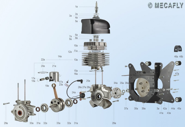
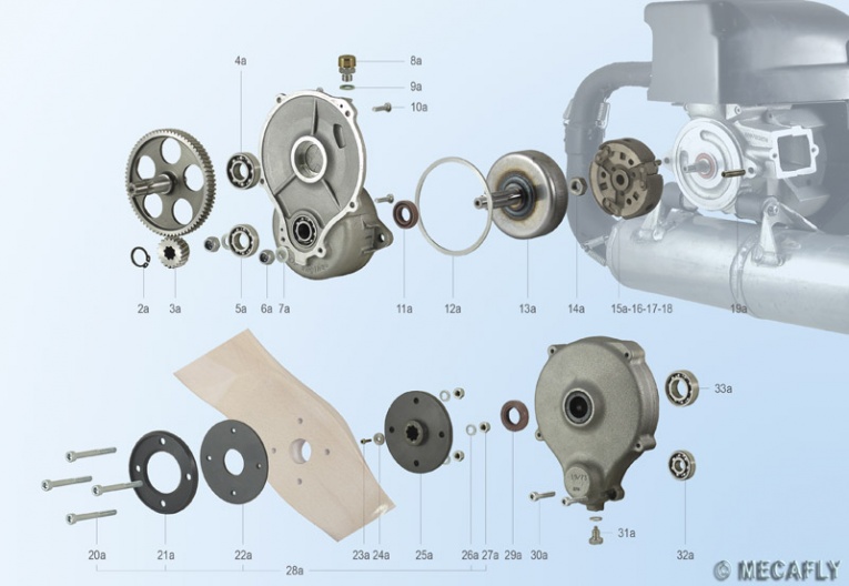
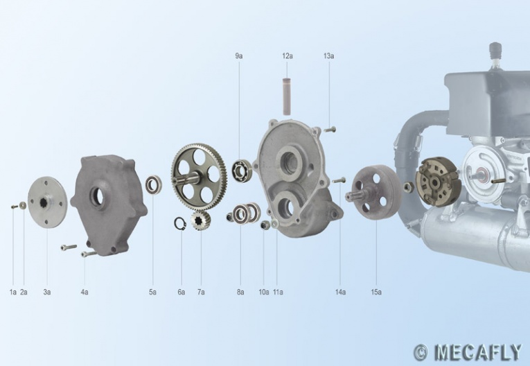
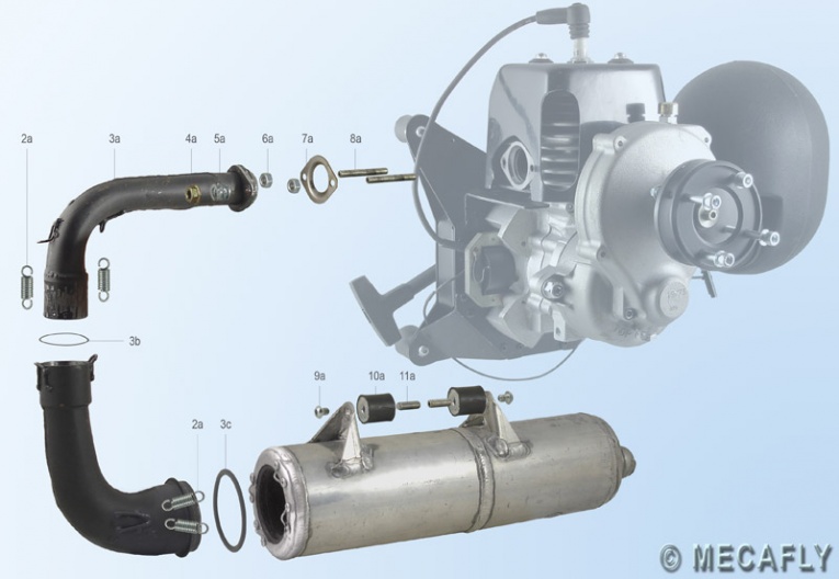
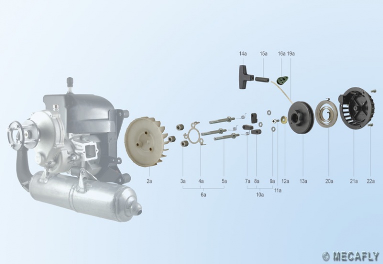
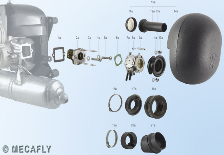
Exploded parts diagrams engine redrive redrive before 2004 exhaust starter carb (go to Mecafly for parts identification)
Bearings, engine – see "Engine main bearings" below
Carburetor – Note: the WG is out of general production and all production may end soon. It is still available from some paramotor shops but is more than double the cost a year ago. The WB may be used in place of the WG and is still available on the open market.
Carburetor idle needle – 1 1/4 turns (1 1/8 turns if above 4,000' MSL) These values are for the initial setting only and should be rich.
Carburetor main jet – size 116 (sea level), size 112 if FSM is installed (sea level). We custom machine jets of all sizes.
Carburetor metering lever value – 0.7mm (0.28"). If your ML diaphragm has a tang instead of a button, set the value to 1.70mm
Carburetor pop-off pressure – 1.2-1.3 Bar (17.5-19.0 psi). Rest pressure must be 0.69 Bar (10 psi) or greater.
Carburetor pop-off spring length, new – 14.85mm Note: old springs can have the same length as new but be defective i.e., be brittle from age = higher pop-off pressure = leaner fuel/air mixture. Typically, old springs will be 0.5 mm shorter. When in doubt, replace it.
Carburetor priming lever depth below top of diaphragm cover < 4.0mm – it should not touch the ML diaphragm in the rest position
Carburetor tubing – 6mm ID x 55cm (fuel tank to inline filter) and 4mm ID x 20cm (inline filter to carburetor
Clutch bell shaft to redrive housing clearance > 29.5mm. See the clutch page for more details on this clearance.
Clutch bell housing minimum thickness 1.2mm
Clutch springs – overall length 31mm. If more than this, replace. The clutch should engage at 2,500 - 3,500 RPM
Clutch seals, bearings, etc. – see "Redrive" below
Coil – see "Ignition coil" below
Compression – see "Engine compression" below
Crankshaft – longer end is the flywheel side
Cylinder gasket squish – 0.60mm-0.70mm (0.024"-0.028") For low octane fuel make the thickness 0.80mm-0.95mm. Engines before June 2003 require 0.80mm-0.85mm. New gaskets compress approx. 30%. This must be noted when calculating the gasket size. Most common sizes are .30mm & .40mm. Excessive gasket thickness is always better than too thin. Too thin a gasket can cause engine damage.
Cylinder head spacers – 6mm x 10.5mm aluminum
Cylinder head studs – long 6mm x 140mm; short 6mm x 120mm
Cylinder head temperature – max 200°C, cruise temp 120°C - 145°C. Temperatures above 150°C should be for less than 1/2 minute or so. If the engine runs hot, use only 100% synthetic oil e.g. Amsoil Dominator.
Cylinder piston sizes – This is a table of the piston sizes (letters) for the corresponding cylinder diameter after boring or honing.
Dimensions of the Top 80 (courtesy of www.tonyfly.com)
Engine compression – about 150 psi (sea level); 135 psi (4,000' MSL). Values can be 10% less without problems. Do NOT put any oil in the cylinder before testing. Compression will be less on a engine that has not been broken-in. Newly rebuilt engines that have not been broken in will show 120 psi or more.
Engine connecting rod, upper bearing, inside diameter, new – 17.0mm. Service limit is about 17.1mm.
Engine cylinder dimensions – This is a table of the piston sizes (letters) for the corresponding cylinder diameter after boring or honing.
Engine main bearings – SKF BB1B 447205A
Engine mounting screws – the screws on the harness side (M6x8) are shorter than on the engine side (M6x10). Use blue threadlock.
Engine main seals – 18 x 28 x 7mm double-lipped type FPJ (after Feb, 2014: 18 x 32 x 7mm) These are specialized seals available only from Miniplane.
Engine mounting screws – the screws on the harness side (M6x8) are shorter than on the engine side (M6x10). Use blue threadlock.
Engine mounts, rubber – UPPER mounts 25mmL x 25mmW; LOWER mounts 30mmL x 30mmW (or 25mmW); all mounts M6 threads
Engine timing – see "Ignition timing" below
Exhaust flange springs/nuts – go here for more information and *how* to tighten.
Exhaust mounts, rubber (2) – 30mm x 30mm, M8 female x 8.5mm, M8 male x 17mm. DO NOT TORQUE THESE DOWN. See torque specifications below.
Exhaust system O-rings – there is one large O-ring where the exhaust pipe enters the muffler. There can be none, one, or two, small O-rings between the two exhaust pipe sections.
Flywheel diameter – see "Ignition flywheel diameter" below
Fuel – premium grade unleaded gasoline, ethanol free. For more info, see the fuel-oil specification page.
Fuel filter – which filter does the best job? Which ones do you avoid? Filter quality is all over the place so pilots have to be careful.
Fuel line/tubing size – Use Tygon® LP1100 Low Permeation Fuel Tubing (ethanol resistant) available from Miniplane-USA. Do NOT use ordinary vinyl tubing as it will become stiff quickly and stress the connections on the tank and engine. Auto parts stores do not have the right type. Be absolutely certain the fuel lines are NOT leaking. A leaking fuel line, especially at the carburetor inlet, will leak air and cause fuel starvation.
- carb to inline filter ID 1/8" (3mm) x OD 3/16" (6mm)
- inline filter to fuel tank ID 3/16" (5mm) x OD 5/16" (8mm)
Fuel & oil specifications – The correct fuel & oil are critical to engine performance and long life. This is a thorough discussion of the issues.
Fuel pump vacuum – 5" H20 (dry) 7" H20 (wet w/ fuel) It should be obvious why paramotors with fuel tanks way below the engine have fuel supply issues.
Horsepower – see "Output of Top 80 engine" below
Hub run out – see "Propeller hub face run out" below
Ignition coil – IDM #150, coil must be installed with secondary wire closest to cylinder head
Ignition coil primary resistance = 1.1 Ohms or less (but not zero)
Ignition coil secondary resistance = 8K Ohms ±10% (measure with a needle stuck into the secondary wire right where it comes out of the coil.) This value can vary depending on the production run but should never be below 8K Ohms at the coil.
Ignition coil + secondary wire resistance = 8K or 17.5K Ohms ±10% (one or the other depending on the type of secondary wire). With our secondary kit installed, the value will be 8.8K Ohms ±10%. Our secondary wire is not the resistor type. IDM makes some secondary wires with resistance and some without.
Ignition coil to flywheel gap – 0.38mm (0.015") Note: The Miniplane website specifies a gap of 0.30mm (0.012") but new engines from the factory have the gap set to 0.38 mm (0.015"). The gap can safely range from 0.35mm - 0.40mm. A smaller gap makes the engine easier to start.
Ignition flywheel diameter – 282.74mm (90mm circumference)
Ignition timing – Official value is 14.5° BTDC or 0.90mm-0.95mm/0.0354"-0.0374" piston distance from TDC or 11.38mm at the flywheel mark at TDC. check timing or change timing The factory method used to initially set the timing gives an advance of 14.5° BTDC +/- 0.5°. Pilots who have set the timing to 17° BTDC measured with a timing light have not reported any problems. Even with the timing set correctly, the actual timing will vary, depending on the rotation speed of the flywheel, the condition of the coil and what the coil gap is. Measured values between 14° and 17° degrees should not cause any issues. For every 1° of timing change, the piston moves 0.1mm (.004") and the flywheel 0.8mm (.032"). The timing specification has a tolerance of 0.05mm (.002") which is 1/2° +/- range in the timing or 14°-15° BTDC.
Muffler springs – Use paraglider line to stretch the springs for replacement/removal. Do NOT use pliers to stretch the springs because this will nick the tempered surface of the spring and weaken it. Here is a video on how to properly do it
Muffler system O-rings – see "Exhaust system O-rings" above
Oil – see our fuel-oil specification page
Output of Top 80 engine – 11 kW (14.8 hp.) at 9,500 RPM at sea level
Overheating – see "Cylinder head temperature" above
Piston ring, clearance between the lands 0.038mm (0.0015")
Piston ring, end gap 0.178mm (0.007") new, max .191mm (.0075")
Piston sizes – see "Cylinder piston sizes" above
Pop-off pressure – see "Carburetor pop-off pressure" above
Power – see "Output of Top 80 engine" above
Propeller hub – the propeller hub must be installed and removed with heat. DO NOT USE FORCE. YOU WILL DEFORM THE HUB AND RUIN IT!
Propeller hub face run out – < 0.013mm (0.0005") A value greater than this will cause propeller vibration, the greater the run out the worse it is.
Propeller shaft run out – < 0.013mm (0.0005") A value greater than this will cause propeller vibration, the greater the run out the worse it is.
Redrive bearings – LARGE GEAR, prop side FAG 6003 C3, engine side FAG 6202 C3; SMALL GEAR, prop side FAG 6200 C3, engine side FAG 6002 C3
Redrive clutch bell housing minimum thickness – see "Clutch bell housing minimum thickness" above
Redrive clutch springs – see "Clutch springs" above
Redrive fill plug relief pressure – 1.5-2.0 psi (new redrive models only). If this relief valve becomes clogged, the redrive will leak oil.
Redrive hub face run out – see "Propeller hub face run out" above
Redrive lubricant – Miniplane specifies 50 ml of SAE 80W-140 gear oil. 75W-90 100% synthetic gear oil may also be used. These are simple, non-hypoid gears. It is rare that redrives ever wear out. Older models of the redrive (before 2004) use grease. These models do not have a drain plug and must be completely disassembled in order to replace the grease.
Redrive ratios – There are five gearbox ratios: 18:74 (1/4.11) 19:73 (1/3.842) 20:72 (1/3.6) 21:71 (1/3.38) 22:70 (1/3.18)
Redrive seals – prop shaft 17mm X 30mm X 7mm; clutch bell 15mm X 28mm X 6mm
Redrive shaft run out – see "Propeller shaft run out" above
Safety net wear – How to minimize wear and tear on the safety net
Seals, engine – see "Engine main seals" above
Secondary wire + coil resistance – see "Coil + secondary wire resistance" above
Secondary wire resistance (only) – 500 or 8K Ohms ±10% The 8K Ohms secondary wire has a resistance of about 570 Ohms/inch (225 Ohms/cm). If the wire from our secondary replacement kit is used, the resistance is about 13 Ohms/inch (5.1 Ohms/cm). After late 2018 Miniplane changed the secondary wire in their coils to one like ours which has very low resistance (<15 Ohms). In 2020, Miniplane changed the wire back to 8K Ohms resistance. Not sure why the changes...
Spark plug gap (all types, all Top 80 models) 0.5mm-0.6 mm. (.020” - .024”) Always set the gap to the minimum. The greater value is the maximum value, not the range. You cannot gap the plug correctly without a wire-type gauge.
Spark plug installation and information
Spark plug type – OLD model cylinder head (14mm thread) Cold flying conditions use the NGK B9ES (2611) or B9EG (3530). Hot flying conditions use the NGK B10ES (7928) or B10EG (3630). The "G" type plugs will help the engine start easier and reduce oil fouling but cost more. Use resistor type plugs e.g. BR9ES if interference is noticed using a 2 way radio. The correct heat range for the plug is necessary to prevent fouling or overheating. Always use RED threadlock on the terminal cap if it is a removable terminal. It will loosen if threadlock is not used, even if it is tightened with a pair of pliers. Some terminals are welded on (flush top surface) and do not need threadlock. The removable terminal is threaded and the screw from the plug is visible in the center of the terminal. For more information, see "Spark plug installation and information" above.
Spark plug type – NEW model cylinder head (10mm thread): NGK CR9EB (6955) This is a resistor-type plug (less radio noise) with a resistance of 4.5K± Ohms
Speed system pulley – Harken H404 (superior to any of the OEM brands, especially Viadana)
Spring removal and installation – see "Muffler springs" above
Squish – See "Cylinder gasket squish" above
Starter cord – 1.25m x 3.0mm Dyneema. It will last years.
Starter cord pulleys – Harken 082 (superior to the OEM Viadana)
Tachometer/hour meter – see "Cylinder head temperature" above. Not having this gauge is like not having an odometer on a car.
Temperature – see "Cylinder head temperature" above
Timing – see "Ignition timing" above
Vibration – A badly damaged prop will cause vibration. However, the usual source is the prop hub which is almost always bent from a prop strike
Weight, dry – 20.5 kg (45 lb.) no fuel, includes the complete Miniplane frame
Torque values
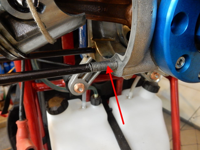
If you don't think you need to learn how to use a torque wrench, check this photo of a cylinder head stud that was pulled right out of the aluminum crankcase by applying too much torque to the cylinder head nut. The threaded hole in the crankcase was ruined. It was an expensive mistake for the owner of this engine that we had to fix. For help, take a look at this video on torque.
Note: The Italian paramotor manufacturers continue to use button-head screws on their engines, regardless whether they are needed or not. Button-head screws have soft heads which make them very easy to strip with a hex bit when attempting to remove them. Replace them with hex-head or socket-head screws, if possible.
A. Conversion charts of Nm to inch-pounds and from Nm to ft. lbs. are easy to find on the Internet. All paramotors are spec'd and manufactured using the metric standard.
B. Torque Tips
- It is SO EASY to over-torque fasteners used in paramotor engines because the threaded holes are all in aluminum.
- Fasteners that compress gaskets must be torqued to the correct value and then re-torqued (30) minutes later. Examples of this type of fastener are head nuts, redrive screws, and crankcase bolts.
- Exhaust springs (Top 80 redrive only) are tightened in a
special way
- Aluminum: Reduce all torque values by 50-60% with aluminum screws or steel screws into "short threads" (less than 10mm into aluminum).
- Reduce torque by 70% or more with screws into plastic.
- WARNING: button-head screws cannot be torqued like ordinary screws. See section "F" below for the correct values.
- The correct torque is very important on bolts/screws that fasten together pieces that have great forces which can separate them e.g. bolts holding on a cylinder head or the nuts holding on a flywheel. Sufficient torque also prevents fasteners from loosening. Many fasteners on ultralight engines cannot be relied upon not to loosen unless other measures are taken, such as the use of threadlock or wire. There is no fastener on a paramotor that would be life threatening if it should come loose but it would be inconvenient, at the least, or cause serious damage to the equipment, at the worst. This is why some nuts are the locking type and why BLUE threadlock should often be used. Use a paint-pen or nail polish to mark important fasteners, like the bolts that hold the engine on the frame. A quick glance will tell you if they have moved (loosened).
- Studs should be installed with red threadlock and torqued only 2-3 Nm. The threadlock is what holds them.
C. Threadlock – read this important page on threadlock and how to use it and when NOT to use it. Use of Blue Threadlock will prevent fasteners from loosening and should be used when possible. Some general exceptions are: head nuts, flywheel and clutch nuts (anything connected to the crankshaft), spark plugs, reed valve and carburetor fasteners, and fasteners that go into blind nuts (you will not be able to remove the fastener because the blind nut will turn). Section F below has additional notes on fasteners that need threadlock.
D. Engines running near or at sea level run hotter and have greater output which causes things to loosen more easily, especially the cylinder head.
E. Torque values of common fasteners. This torque table from Miniplane IT can also be consulted. Fasteners must be perfectly dry and clean. I recommend reducing the torque by 20% if the fasteners have threadlock or any sort of lubricant or sealant applied.
- M4 2.5-3 Nm (use caution with these small fasteners)
- M5 4-5 Nm
- M6 9-11 Nm
- M7 10 Nm
- M8 20-24 Nm
F. Top 80 torque values of various parts (other paramotors are similar)
Miniplane back plate to frame – 2 Nm Use a *very small* amount of blue threadlock on the (6) screws to keep them from vibrating out. Too much and the threaded stud will turn (bad) when you attempt to remove them. Heating the screw with a torch is the only way to remove them if this happens.
Carburetor mounting studs – 4 Nm. It is easy to strip the threads in the reed valve body when installing these screws so be careful of the torque. Use of threadlock is not necessary. It is rare that these screws ever need to be removed. If you break them, we have replacements (cheaper than buying a completely new reed valve body).
Carburetor/air box mounting nuts - 0.9 Nm (8 in-lbs.) Over-tightening these nuts deforms both the air box gasket (which will then jam the choke in either the open or closed position) and/or the gasket between the carburetor and the reed valve body. If these nuts are too loose, the carburetor will leak like crazy.
Clutch nut 38-40 Nm – Do not use threadlock on this nut.
Cooling air duct (cooling shroud) locknuts – DO NOT TORQUE THESE DOWN. They should just be snug (5 in-lbs./0.5 Nm). Put RTV between the bottom washer and shroud. The top metal washer should have a rubber washer between it and the shroud. The vibrations from the engine are intense and direct metal to metal contact must be avoided.
Cooling box to crankcase (4) bolts 10 Nm – threadlock is not needed
Cooling fan/starter to flywheel screws – see "Finger screws" below.
Cylinder head nuts 9 Nm (80 in-lbs.) Tighten in a cross pattern to 4 Nm and then to 9 Nm. Note: do not use thread locking compounds on these nuts. It is best to use a 1/4" beam-type torque wrench. Wait (10) minutes after tightening and then re-tighten to 9 Nm. Assembly order: Short bolt – washer, nut; Long bolt – spacer, washer, nut. After engine assembly, put the large metal washer on the stud, then the cooling air duct, plastic washer, and locknut. Failure to get the order correctly will damage the cowling. The locknuts holding the air duct should be just snug (2-3 Nm). If they are torqued down the same as the nuts beneath, they will damage the air duct.
Engine case screws (6) – 5 Nm
Engine mounting button-head screws – 3 Nm Be sure to use BLUE threadlock on these critical fasteners.
Exhaust button-head screws – 5 Nm Install these AFTER the exhaust flange nuts have been tightened
Exhaust flange springs/nuts – see this page for notes and how to tighten.
Exhaust flange studs – 2 Nm. Use RED (high strength) threadlock on these studs or they will loosen.
Finger screws – 10 Nm A 10mm deep socket must be used to tighten these screws. Threadlock is not needed.
Flywheel nut 38 - 40 Nm Temporary torque for setting timing 2 Nm. Do not use threadlock on this nut!
Frame to engine mounting button-head screws – see "Engine mounting button-head screws" above.
Muffler mounting button-head screws – 10 Nm Note: BLUE threadlock must be used on these screws.
Muffler rubber mounts (in engine) – Tighten firmly with adjustable pliers that grip the steel washer on the side that has the stud. Use BLUE threadlock on the stud – this is very important.
Propeller bolts 6-10 Nm – It is better to be on the loose side when tightening. Note: failure to keep these torqued properly can destroy the hub. Note: A ordinary torque wrench cannot be used on the engine side. Use a hex bit with the torque wrench on the prop side. Do not over-tighten. Wooden propellers are particularly prone to loosening and must be checked regularly. Replace the locking nuts when they turn easily or use BLUE threadlock. Make sure the rubber washer is under the outer flange and NOT between the propeller and the hub/spacer.
Propeller hub center screw 9-10 NM – Do not use threadlock on this screw. Go here for critical information on removal or installation.
Redrive fill & drain plugs – 5-6 Nm. Note: drain/fill plugs are not designed for high torque values. It is easy to strip them. Never use threadlock on drain/fill plugs.
Redrive nuts (the nuts that go on the studs that hold the redrive to the engine) – 20-24 Nm When assembling be certain to check the clutch for drag before torqueing the nuts down.
Redrive screws – 4 Nm for the (4) 5mm screws, 10 Nm for the (2) 6mm screws. Do NOT use threadlock on these screws!
Redrive studs (the two that hold it to the engine) – these studs should be removed and reinstalled with red threadlock. If the studs cannot be removed with moderate force, you can leave them alone. DO NOT TORQUE THESE STUDS DOWN. Only 2-3 Nm should be used.
Reed valve screws – 2.5 Nm (22 in lbs.) You must use BLUE threadlock on these screws. The reed valve body must be firmly attached to the crankcase for fuel pump to work.
Spark Plug – 14mm plug: 25 Nm (18 ft. lb.) 10mm plug: 10 Nm (9 ft. lb.) If you do not have a torque wrench, the plug is new, and you do not have a CHT installed you may use this method to tighten it. 1. First hand tighten 2. Tighten with a wrench an additional 90-120 degrees. DO NOT USE ANTI-SEIZE COMPOUNDS ON SPARK PLUG THREADS. However, be sure to use RED threadlock on the spark plug terminal that screws on to the top of the spark plug (if it has a removable terminal). It will loosen, even if it is tightened with a pair of pliers, if threadlock is not used. I have found out that they, too, will loosen if the terminal is not unscrewed and red threadlock applied. Most newer plugs have the terminals permanently attached. These terminals cannot loosen. You can tell the difference by looking at the top of the terminal. The threaded terminal is not flush and the male threads are visible. A sure sign that a spark plug has not been properly torqued is the presence of black gunk near the base (where the washer is/was) of the plug. This part of the plug should be CLEAN.
Starter center screw – 2 Nm Be certain to apply Blue Threadlock to this screw.
Starter mounting screws – 2-3 Nm Do NOT use threadlock. It is not needed because the screws already have lock washers.
Maintenance
If you are storing your paramotor for more than a few weeks, purge the fuel system. Ethanol fuels wrecks the soft parts in all carburetors over time. Walbro warns about the damage done to carburetors that are stored with any fuel left in them.
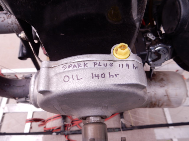
Changing the spark plug and changing the redrive oil are the (2) most frequent maintenance items on most paramotors. Use a Sharpie to write reminders on the top of the redrive (or other semi-flat area). Any other method will not be as effective. They are easily removed/changed with mineral spirits. This way, you won't forget. You have an hour meter/tachometer installed right? Note: go to this page if you are wondering why the yellow plug is in the redrive.
NEW engines – Miniplane QC is sketchy and factory technicians routinely make serious errors assembling the Top 80. Here are the most common problems that I have seen:
- Reed valve body mounting screws not installed with blue threadlock nor properly torqued down (this causes poor fuel pump operation).
- Head nuts not properly torqued down (9 Nm).
- Studs in engine not installed with red threadlock: Redrive mounting studs and exhaust port studs should be checked for threadlock. If they can be easily removed, they WILL come out at the most inconvenient time. See the torque information above for how to do it.
- Redrive oil leaks – I have had redrives come in where the case halves had not been properly sealed with RTV. If you have clean oil going everywhere, you have a redrive that was not assembled properly at the factory. Contact your dealer!
- Muffler button-head mounting screws – Remove them, put blue threadlock on them, and reassemble. Just snug them up. Do NOT torque them as you would an ordinary 8mm fastener. The threadlock is what holds the screws in place.
- Carburetor metering lever height incorrect.
- Defective kill switch wire.
- Clutch drag due to incorrect/defective parts.
After the first 10 hours
- Change the oil in the redrive
- Give the paramotor a careful lookover for loose fittings, especially the motor mount screws (both sides)
- Cylinder head nuts – check torque *THESE NUTS LOOSEN AND MUST BE CHECKED REGULARLY* If they get loose, all sorts of bad things happen.
Every year
- Rebuild the carburetor, be sure to check the pop-off spring for the correct length. The fuel pump inside the carburetor will not work properly unless the carburetor is rebuilt often.
- Replace the inline fuel filter.
- Change the oil in the redrive.
- Replace the spark plug.
- Check the ignition if there is any question about engine power
- Replace fuel system lines if ethanol gasoline is used and they are stiff. Hardened lines put a great stress on connected parts.
- Check the torque of the cylinder head nuts, especially if you run your engine at or near sea level.
- Closely examine the ignition wiring and connectors and make sure there are no broken or loose wires.
Every 25 hours
- Muffler anti-vibration (rubber) mounts – regularly check these to be sure they are not broken or loose. The studs going into the crankcase can loosen after many hours and chew up the aluminum threads. Use high strength (RED) threadlock on these studs.
- Starter pulleys – these pulleys will self-destruct if the center bushing is not regularly lubricated with white lithium grease.
Every 50 hours
- Rebuild the carburetor – a rebuild should be done yearly at a minimum, even if the paramotor is not used. A rebuild can be postponed depending on the fuel used. If the FSM is used, carburetor rebuilds may be done at greater intervals. It is time to rebuild when idle becomes erratic or impossible and engine temperature begins to climb above average values.
- Replace spark plug
- Exhaust flange gasket – Made of copper. Check for cracks and excessive wear. If there are lots of black oil drips in the area, there is also an air leak and it should be fixed. The flange gasket/cylinder head joint should be sealed with high temp sealant e.g. Ultra Grey, as needed. This gasket gradually wears out and will crack and leak if left on too long or if the exhaust flange springs are compressed too tightly.
- Starter – The starter help page has the details on how to lubricate the starter. Generally, remove and lubricate the center bushing with white lithium grease. DO NOT OVER LUBRICATE. Use light machine oil on the spring instead of grease. All grease does is collect dirt and gums up the spring, making it much harder to wind up. Do people who repair clocks use grease on the main spring or fine oil? Think about it. Do not wait until the starter fails to work – it will be too late.
- Redrive oil – drain & replace. Be sure to clean the magnetic tip of the drain plug and check the pressure relief valve.
Every 100 hours - THIS IS A VERY IMPORTANT MAINTENANCE INTERVAL
- Cylinder head and piston de-carbonizing – Alex Varv shows how to do it without removing the cylinder. However, I do not recommend using any sealant between the cylinder and cylinder head. It is unnecessary. I am not sure why Alex recommends this. Maybe his engine has problems?
- Clutch links, springs, and the inner hub should be checked for excessive wear. If the links can be wiggled around, the clutch must be removed and carefully examined. Go to the clutch page for more details. Reassemble with anti-seize compound.
- Compression check – this is the #1 way to know what condition the cylinder, piston, and rings are. If it is out of specs, replace everything or have the cylinder re-bored and honed at this shop and get an oversized piston from Miniplane-USA.
- Exhaust system O-rings – Check both joints in the exhaust system pipe for oil leaks. If there is any sign of black oil around these joints, disassemble the exhaust system. The top one O-ring, especially, disintegrates quickly. Note: some Top 80 models have (2) upper O-rings in the exhaust system.
- Ignition secondary continuity check – you can expect the secondary wire to fail by this time if you have not installed our replacement secondary wire kit.
- Re-drive studs in the engine case – make sure they are not loose. If they are, remove and install with red threadlock. These are SS and may fail after many hours and go into the prop. Replacing them with hardened alloy steel studs may be done.
- Piston roller-cage bearing and wrist pin replacement – This is a critical service.
- Piston ring replacement, if needed (see the ring page). If compression is down by over 15%, it is better to replace the piston, ring, and cylinder.
- Prop bolts – check for tightness. Too tight is as bad as too loose. When they are too tight, much greater stress is put on the bearings. The rubber gasket is important in absorbing some of the vibration from an unbalanced propeller.
- Reed valve petals – take off the carburetor and shine a light into the reed valve body and be sure the petals are 100% intact. However, it is better to remove the reed valve body and carefully examine the petals. If a petal breaks off and goes through the engine, it can damage things.
Every 150 hours
- Hone cylinder – If compression is low, Miniplane suggests that the cylinder be honed. It is about the same cost to just replace everything unless you know how to hone your own cylinders. You will also need the tools to measure the diameter of the honed cylinder to be certain you do not need an oversized piston. If the cylinder is honed/bored, an oversized piston is probably needed.
Every 200 hours
- Clutch – if the clutch engages at idle or is noisy, the only practical solution is to replace it.
- Cooling ductwork on engine – the aluminum fins that are a part of the cooling box will eventually break loose. They are not critical parts.
- Cooling fan check – Miniplane recommends replacing it but I am not sure why this needs to be done.
- Crankcase oil seals – replace if leaking beyond an acceptable amount.
- Cylinder – examine the cylinder wall for the presence of honing (the cross-hatch pattern). If it is barely visible, replace or re-hone the cylinder.
- Frame – check it carefully for cracks.
- Piston, wrist pin, bearing, and circlips – replace.
- Redrives made before 2004 – it is a good idea to replace the grease at this time or every five years or so. See Mark Kubisch's notes.
- Reed valve petals – replace them if there is any question of their condition (the engine will idle and start better). A missing petal will prevent the engine from reaching full power if it runs/starts at all.
Every 400 hours
- Completely rebuild the engine i.e. new main bearings, crankshaft, seals, piston, cylinder, upper connecting rod bearing and wrist pin, etc.
![]()

