


Ignition troubleshooting for 2 stroke paramotor engines
by Had Robinson
updated August 3, 2023
Discussion
The following information is primarily for the Top 80, Minari, Vittorazi, and some Polini Thor models. Other engines are similar but the wire colors may be different.
Generally, the most overlooked ignition problem on all engines is the condition of the spark plug. They are so inexpensive that replacing a spark plug should be one of the first things you do, especially if it has more than 20 hours on it. Pilots should always carry a spare and have the necessary tools on hand to change the spark plug and accurately set the gap. Use a torque wrench to ensure that the plug is not over/under-tightened.
If the spark plug is not torqued down enough, it will leak and engine performance will suffer. It can also cause overheating. You can tell if it is leaking by removing the plug and checking the aluminum spacer washer. If there is oil beyond the edge of the spark plug, you have a leak. Note: Excessive torque can destroy the threads on the cylinder. Pilots should invest in a torque wrench if they plan to service the spark plug.
Plugs out of the box do NOT have the correct gap – check them before installation. Use a spark plug gauge to set the gap correctly (it uses a gauged wire to check the gap rather than a flat tab). Commonly available gauges are not of the wire-type and should not be used.
Most paramotors do not have high energy ignition systems (e.g. capacitor discharge/computer controlled system) so they are very sensitive to plug, coil, or wire problems.
For some introductory information about engine ignition systems, visit this helpful site.
Here is the specification sheet from IDM, the manufacturer of the coil used in the Top 80 engine and many others including the Minari, Vittorazi, and Simonini. The Polini engines (except the Thor 190) uses a different and higher output IDM ignition known as a magneto system. Within the last few years, popular engine manufacturers have upgraded the ignition systems on some of their engine models. The typical paramotor ignition is very simple. There are only 2 or 3 wires coming out of the coil. The thick wire is the secondary wire which goes to spark plug. The thin wire is the primary wire which connects to the kill switch. The other thin wire if present (usually black) is the ground wire. Note: some coils do not have this wire and are grounded internally. If the primary wire touches ground (the engine or frame), the coil shorts out and no spark is generated = the kill switch.
Tools needed: Digital voltmeter & some test leads. Harbor Freight has these tools for less than $15 U.S. Sometimes these tools are free if you show up at the right time and fog a mirror. If you do not know how to measure resistance, Fluke has this site for the basic "how-to".
Magneto systems How do you tell if you have a magneto system? The Polini Thor engines (except the 190) use a magneto system. It is easy to tell which you have. All ignition systems have the secondary wire connected directly to the coil. Non-magneto systems have the coil mounted right next to the flywheel. Magneto systems have the coil mounted away from the flywheel, usually close to the spark plug. Magneto systems have a small exciter coil mounted adjacent to the flywheel which generates a low voltage pulse that feeds the main coil. This pulse generates the high voltage spark. For troubleshooting information on magneto ignition and charging systems including wire identification, see the magneto features & troubleshooting page.
A. Primary wire test
An engine manual may be required if help is needed to identify the primary wire. Measure the resistance of the coil primary wire to ground (e.g. an engine cooling fin). Disconnect the primary wire from any other wires. Some coils are polarity sensitive so you may have to reverse the leads of the test instrument in order to get a reading. If the primary wire has infinite resistance to ground: 1.) the coil is likely bad and will have to be replaced OR 2.) the primary wire could be broken before it enters the coil. Low primary resistance is particularly hard to measure accurately but, thankfully, it is a rare problem. Remember that manufacturers are constantly changing things so the following specifications can vary.
- Top 80, Minari, and the Thor 190: 5 Ohms or less but not zero (the black wire going from the coil to the kill switch)
- Thor 100, 130, 200, 250: 1K+ Ohms (the light blue wire coming out of the coil) Note: The coil has electronics in it which makes this value difficult to measure so any value greater than 1K Ohms is OK.
- Other engines: any value but ZERO.
B. Secondary wire and coil test
The easiest and best way to test the ignition system is with the ignition spark tester tool which is available from AutoZone or eBay for under $10.
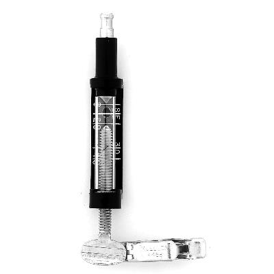
Set the tester to 20 KV (kilovolts), remove the spark plug, connect the tester, and spin the engine. If possible, use a drill to turn the engine at 400-600 RPM. Using the manual or electric starter on the engine may not turn it fast enough to perform an adequate test. There must be a bright white spark between the two points inside the tester. If the test passes, you know the ignition is probably OK. If it fails, continue with the tests below to determine which component(s) is faulty.
Alternately, if pilots want to do a quick check of the ignition coil without the tester, get a used spark plug and set the gap to +0.045" and repeat the above test. The greater gap will insure that the coil has the ability to produce a good spark while under load. If there is a good spark, the coil is probably OK but using the tester provides a better test.
With a digital multimeter (<$10 from Harbor Freight), measure the resistance from the metal connector inside the spark plug boot to one of the cooling fins on the engine (ground).
- Top 80, Thor 190, Minari (most models): 17K Ohms. Some newer models have at resistance of 8K Ohms
- Other paramotors will have a resistance of between 7K and 10K Ohms between engine ground and the spark plug cap terminal
If you get a low resistance value, you should determine if the coil is OK with these steps:
This test will make a harmless pinhole in the wire and will not cause a problem. Stick a sharp pin or needle into the secondary wire about 3" from the coil and measure the resistance from the pin or needle to the engine ground e.g. one of the aluminum cooling fins on the cylinder. It should be about 10K Ohms (the resistance of a good coil PLUS the resistance of 3" of secondary wire in the typical IDM ignition coil. Other engines may vary but not more than 10-20%. If you do not see any resistance at first, withdraw the needle and stick it in again closer to the coil. If it is less than 10% of 10K Ohms (or open/infinite) in an IDM coil, the entire coil assembly must be replaced. Other engines should have a coil resistance value close to this.
Remember that an engine may start and run if the coil is bad but not at, or near, full throttle.
If the secondary wire is open (no resistance to ground), the coil is probably OK. If this is the case, you can replace the wire rather than go to the trouble and expense of replacing the entire coil assembly. If the coil must be replaced, to the this page. An internal break in the secondary wire will cause missing and a drop in engine output at high engine loading. It becomes more acute as the engine heats up and pressures increase inside the cylinder. When the break gets sufficiently wide through burning of the ends, the spark cannot jump the gap in the wire, the engine will not start and the coil may be damaged from internal overvoltage.
If you choose to replace the secondary wire, it is first a good idea to find out where the open or break is. To do this, take a sharp sewing needle and gently shove it about 1/2 way through the wire and about 1/2 the way back to the oil. With the digital ohmmeter, see if there is resistance and how much. If there is resistance, it means that the coil is probably OK. If there is no resistance, move the needle 1/2 way back towards the coil. Continue moving the needle back towards the coil until you have resistance of some value. The actual value will depend how far back you go to the coil. The value can range from about 9K-17K Ohms. If there is no resistance when measured 4" or less from the coil, the technique used to temporarily repair the secondary wire will not work as we need a short stub that is good coming out of the coil. (Note: the complete replacement of the secondary wire does not require a secondary wire stub.)
Failed Test?
Here is a photo of a bad ignition coil from a recent Top 80. The resistance reads 7.7K Ohms from the spark plug boot to the coil ground, less than half of specifications. The coil was new but was incorrectly installed so that the tips of the coil contacted the flywheel. This quickly destroyed the center post and heated up the coil until the internal wire insulation failed and the coil shorted out to ground. The resistance of the carbon-core secondary wire used by Miniplane is 8.5K Ohms ±10%.

Sometimes a small crack or cut in the secondary wire insulation will allow
the high voltage to jump to ground rather than be carried to the spark plug.
To check for this, remove the spark plug, reconnect it, and hold the base of
the plug firmly against the top of the engine. Place the paramotor in
a darkened area and pull quickly on the starter while looking at various
parts of the coil and secondary wire. There should ONLY be a bright
spark across the spark plug gap and nowhere else.
As the load of the engine increases, the density of the fuel/air mix in the cylinder increases. As the density increases, the spark gap breakdown voltage increases. This is why the
ignition system must be in top condition if full power is to be realized. Those who are curious about the principles of how the spark plug works in an engine can read this
technical document from the Society of Automotive Engineers.
Note: Miniplane
and other manufacturers recommend that pilots never remove the spark plug from the secondary wire and then crank the engine because very high voltages can be created
which can destroy the coil if these voltages are not shunted to ground directly through a spark plug or a test lead connected from the metal clip
inside the spark plug cap.
The
use of a carbon-core instead of copper increases the resistance of the
secondary circuit but helps suppress ignition noise in nearby radios caused
by the spark. This special kind of high voltage wiring has a
resistance of about 3,000 Ohms/ft. The downside is that the core is
fragile, will break, and then eventually burn out. The engine will run
with a broken core but high end performance deteriorates eventually as the
spark weakens. The ignition will eventually fail with time because, as
the engine runs, the gap between the broken core ends will widen as the ends
burn. That
is, the high voltage arc will gradually burn the core ends away from each
other increasing the gap until the spark voltage is insufficient to jump
across the gap in the core. When this happens a new
secondary wire
can be installed. Replacing the entire coil is much more difficult
than replacing/fixing the secondary wire.
Pilots often notice some
soot under the spark plug cap. It is actually pulverized rubber that is created by
the severe vibration of the spark plug chewing away at the inside of the
spark plug cap. You can
replace the secondary wire with an automotive type heavy duty wire and
cap and this problem will be much less.
C. Secondary wire permanent replacement
Please go this page for a permanent replacement of the secondary wire of coils made by IDM. This is what all pilots should do if their secondary wire has gone bad, rather than replace a perfectly good coil.
D. Secondary wire temporary field repair
A field repair of a bad secondary wire can easily be made if the coil is good. Most of the secondary wire is located far from any metal parts so using high tension replacement wire is
unnecessary.
Use the following procedure to find the
break is in the
secondary wire (where to repair it) and, at the same time, to check whether the coil is good. It is expensive and difficult to replace the coil and a waste if just the secondary wire is bad.
Connect a fine needle to one of the probes of the ohmmeter and, starting at the spark plug connection, stick the needle into the wire every 1/2" or so, moving back towards the coil. When some resistance is indicated (see specifications), that will be the approximate location of the break in the carbon-core. If zero resistance or less than specifications is found going all of the way back to the high tension post in the coil, the coil is defective and this repair is useless. A new coil must be installed.
The side towards the coil from the last pin location will be
useable for the repair. Carefully split open about an 1.5" of the wire
at this point with a razor blade to expose about an inch of the end of the
broken core that goes to the coil. Pull up about 3/4" of the intact
carbon-core. The good part of the core must be lifted out of the
insulation. Do NOT pull on the core or it can break.
Cut a
piece of ordinary #18 stranded automotive wire long enough to go from the
break to the spark plug cap. Add about an inch or two. Strip the
ends about 3/4". Place one stripped end of the new wire in the bottom
of the split in the secondary wire. Now, firmly press the carbon-core
down on top of it. Carefully hold the split closed so that
the new and old wires are firmly touching each other. The core and the
wire should overlap each other about 3/4". DO NOT USE ANY SEALANT OR
GLUE IN OR ON THE SPLIT. However, for the obsessive types, go to the hardware store and buy a tube of ALNOX brand conductive grease
(used by electricians) and coat both wires with it. It will guarantee
a good connection between them. Now, close up the split in the
secondary wire with electrical tape. Wrap it very tightly.
Drill a hole the same diameter as the new wire in the top of the spark plug cap all the way through. Stick the other end of the new wire in the cap until it sticks out about 1/2" inside.
Firmly wrap the new wire to the non-working secondary wire with electrical tape. Reconnect everything. Be sure to firmly push the cap onto the spark plug using a slight twisting
motion. This will crush the stranded wire out so that it will firmly touch the top of the spark plug. Now you can seal the hole in the cap with silicone
caulk so that the wire does not shake
out. DO NOT SEAL ANYTHING ON THE INSIDE OF THE CAP.
This repair will hold up
for about 50 hours of engine time especially if the new wire is
firmly wrapped to the old and the spark plug cap is not worn out. The
reason the field repair fails is that the new wire going into the top of the
spark plug boot gets chewed away by engine vibration. However, a new wire could be
spliced to the field repair wire and re-inserted into the cap.
Obsessive-compulsive types could do away with the spark plug boot entirely, solder the new wire to a ring-terminal, and put it under that screw-on terminal. This repair would probably last 100's of hours. Anyway, insulated spark plug boots in ultralight aviation serve no purpose except to keep noodle-heads from shocking themselves when the engine is idling and on the ground. Protection from shorting out in the rain? If you fly in the rain – good luck anyway. The reason for any of this is due to Miniplanes use of lawnmower-quality ignition parts.
The break in this wire occurred right next to the wire anchor on the spark plug side.
Note: The Top 80 has severe vibration and you must be careful to anchor the secondary wire at its original locations. Failure to do so will cause premature failure of the secondary wire.
E. Testing the Kill Switch
When the kill switch is pushed, the primary wire of the coil is grounded. Disconnect the wire going to the kill switch and measure its resistance to ground when it is pushed. It should be 0-1 Ohms. If it is always grounded or always open, the kill switch wire/button will need to be serviced. Rarely, the primary wire or the connection to the kill switch wiring can be defective. Just because a connector feels "tight", the wiring inside may be severed or pulled away from the conductive parts of the connector.
An alternative way to test the kill circuit is to set things up per the above (remove the spark plug, reconnect the spark plug, etc.). Push and hold the kill switch while pulling the starter. There should be no spark at the spark plug. Release the switch and pull the starter. A spark at the plug should be seen.
F. Spark plug Problems
This
is another major source of problems for pilots. Time after time I see spark
plugs incorrectly gapped or fouled. The
ignition systems on paramotors are NOT high energy systems like in a car.
Therefore, pilots must be certain that the
plug gap is correct and that the plug is functioning properly.
Failure to replace/gap spark plugs is the most common mistake made by
pilots.
Just recently, a experienced pilot was complaining about high end
performance on his Top 80. We took the plug out and measured the gap.
It was over .030” – way too much. The spark was being quenched under
high load (high cylinder pressures) and the engine would stutter badly. The
proper gap is .020” - .024” (0.5mm – 0.6mm). The pilot properly gapped his
spark plug and the engine ran perfectly – with more power than he had
hitherto experienced. Plugs should be replaced after 25 hours. Of course, how will you know how many hours the plug has unless you keep a log and have an hour meter/tachometer?
The severe vibration of a running paramotor can not only destroy the secondary wire after many hours but can also damage the plug itself by breaking internal connections inside. When troubleshooting ignition problems, you should also be sure that the spark plug internal resistance is not more than about 30 Ohms. If it is open (no resistance) change the plug even though the engine may still start. High load performance will also suffer. Always use the spark plug specified by the engine manufacturer. They engineered the engine and know which spark plug will give you the best performance.
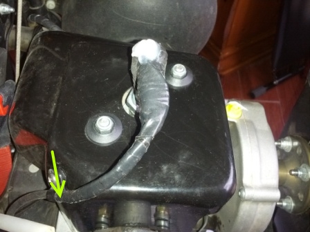
G. Grounding Problems
Some paramotors (not the Top 80) may fail to start/run because of ground loops or open grounds. Generally, you want to be certain that the motor and frame are bonded together electrically, e.g., a #14 wire with ring or spade connectors attached at each end which are firmly attached to screws/bolts on the frame and the motor (remove all paint, if necessary, beneath the screw/bolt).
If this is not done, connections for grounding the coil and other electrical devices may not work reliably. How the ground is done varies from paramotor to paramotor. The rubber mounts between the motor and frame effectively isolate the two which is why they need to be bonded together with a bonding wire. The resistance from the ignition coil to the aluminum frame of the engine must be less than 1 ohm. When you disconnect the kill switch from the coil, the kill switch circuit must be “open” = no resistance and 1-3 Ohms when the kill button is pushed.
![]()