

Rebuilding a paramotor
by Had Robinson
updated December 31, 2025
Introduction
If you have never taken apart a small engine, like a lawnmower or pulled an alternator or starter out of your car, these pages are not for you. If that is the case, you will have to pay an experienced chainsaw mechanic where you live to do the job or, as a last resort, send the engine to us. On the other hand, if you do know what a torque wrench does and how to gap a spark plug these pages will provide the adequate information and steps to service any paramotor.
All Italian paramotors share many parts in common, including maintenance and service procedures. Ignition systems, for example, are all made by IDM with minor variation between brands. Nearly all Italian paramotors have either a redrive or a belt drive system with a clutch. If you learn how to service a Top 80, for example, you can easily service any other make of paramotor.
When should major maintenance like a rebuild be done? The schedules given in paramotor manuals are general in nature. They do not take into account every possible operating condition a pilot might experience. When in doubt about when to rebuild follow the manufacturer's instructions and then information from this website. It is very important to follow the maintenance intervals given by all manufacturers. This site has them for the Top 80, Polini Thor models, Vittorazi Moster 185, Minari, Air Conception, and Simonini. If mechanics are something you may be unfamiliar with, this photo from HappyWrench.com can help.
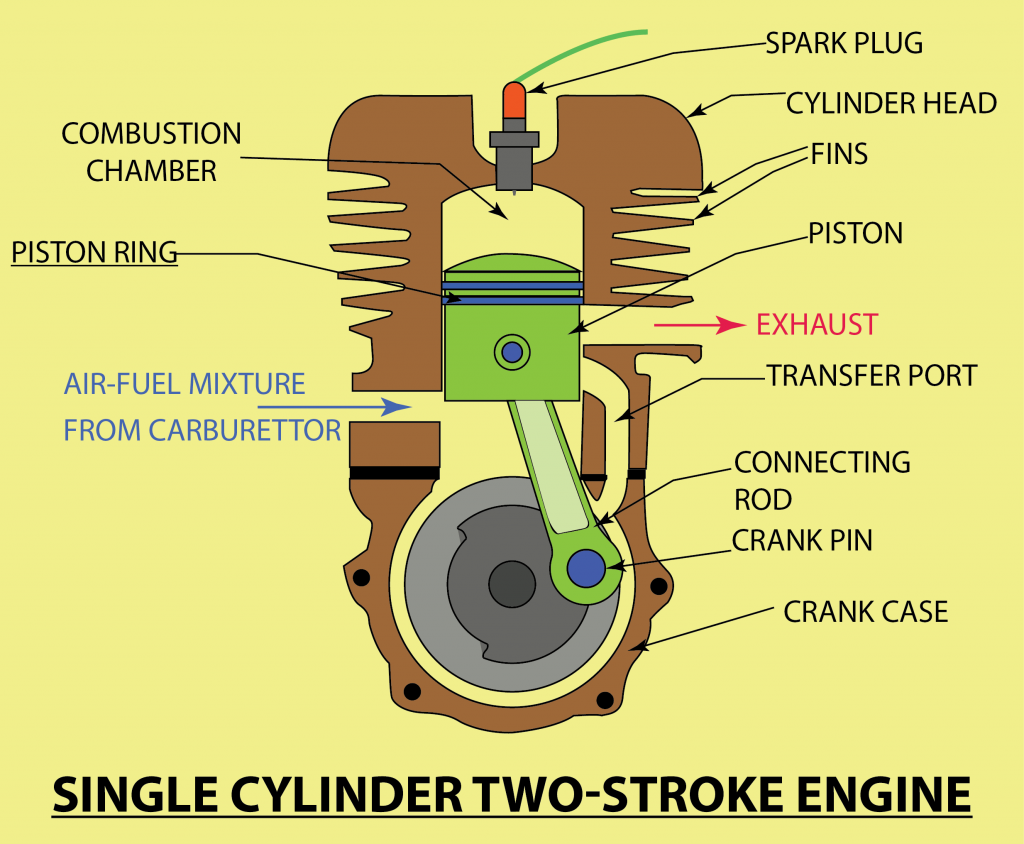
Below is an animated photo of a running 2 stroke engine from Wiki:
In general, if the engine makes any strange clanking or knocking sounds, it is time take it apart and see what is the problem. Typically, these types of sounds are warnings that complete destruction of the engine is at hand. The usual culprit is the upper connecting rod bearing. For example, noticing a marked decrease in performance or engine compression of 15-20% may only require a new piston, rings, wrist pin, and cylinder a.k.a. a top end rebuild.
If you are not that experienced in tearing an engine apart, MCBperformance.com has these tips.
There are basically two types of rebuilds that are done on these engines:
- Top-end rebuild – at a minimum, the upper connecting rod bearing and wrist pin are replaced at the interval specified in the engine manufacturer's specifications. If the piston is damaged in any way, the piston and ring(s) are replaced. If the honing marks on the cylinder are worn away more than about 25%, it also is replaced. For the more ambitious mechanics, the cylinder can be rehoned with a brush hone.
- Complete rebuild – this type of rebuild is required if there are any problems with the crankshaft bearings or with the lower connecting rod bearing or the connecting rod, itself. It is not possible to replace just the lower bearing because the two crankshaft halves are pressed together with tremendous force and cannot be separated in order to remove/replace the connecting rod. When the cylinder and piston are removed, the connecting rod can be examined. It is normal for it to have side to side movement but it must not have any up and down movement.
A pilot should not attempt a complete rebuild/overhaul unless he is willing to invest in the specialized tools needed to separate crankcase halves, reinstall a crankshaft, or remove flywheels and drive pulleys. A specific engine may require unique tools to do some of these tasks. If there was a way to avoid these particular and often expensive tools, it is be posted on these pages. For some special tools needed, workarounds and notes on how to make your own are given on this page.
Steps given here are general for all motors. Minor details may be vary for each brand of engine. For example, some engines have forced air cooling and some do not.
If you find yourself struggling to remove or install a part, you are likely not doing it correctly. *Stop* and do some research. With heat (i.e. a propane or oxyacetylene torch) and the right tools these engines come apart quickly and go back together easily.
THERE IS NO EASY WAY TO DO ENGINE REBUILDS! WATCHING A 20 MINUTE YOUTUBE WON'T CUT IT. You must have experience and modest mechanical skills.
Tip: When disassembling an engine, it helps to put the small parts of each group e.g. ignition, carburetor, exhaust, etc. in a small container. It is easy to get things mixed up if they are in a big pile. Taking photos as you disassemble the engine for later reference during reassembly is a good idea unless you have a photographic memory.
Italian paramotor engines are finicky, documentation and service info is often sketchy or inscrutable – pilots have to get over it. Every brand of paramotor has demons and you have to have the patience to find out what they are and how to work with them. These engines are NOT made by Toyota or Honda. Often, the Italians will copy/steal designs pioneered by American or Japanese engine makers and charge 4X the price for a part that is identical but inferior. Vittorazi, for example, has used photographs and service information from this website without acknowledgement or permission.
With anything mechanical, cleanliness is next to godliness.
The photographs shown on these pages are typical of the various paramotors.
Tools
Besides these essential tools, the following tools will be needed for a complete rebuild, including the special tools on the bearing replacement page.
- case splitter
- infrared laser thermometer
- propane or oxy-acetylene torch
- a 3/8" impact wrench – A 3/8" battery operated impact wrench with the special metric sockets will make the job of removing the flywheel and clutch nuts fast and easy without having to hold the flywheel or clutch. Using an impact wrench with a gear or wheel puller is vastly preferred to cranking things with a breaker bar. Note: An impact wrench must never be used to re-install any bolts or nuts! A torque wrench and some manner of holding the rotating part (flywheel, pulley, etc.) must be used.
- various small metric taps are needed to clean the threaded holes on case halves of threadlock and other debris or goo.
- blind crank bearing/gear puller – this tool may be required if a shaft comes out with the bearing attached. Search on eBay for "crank bearing/gear puller". Harbor Freight also makes a similar tool.
Here are the links for parts (including special tools) for the Italian engines. The special tools are needed to remove flywheels, clutches, pulleys, and redrives.
Steps
Top end repair/replacement ONLY - this will take you to the necessary steps to replace/repair the cylinder, piston, and head.
Crankcase seal replacement generally requires that that the engine case halves be split.
Here are (2) helpful videos on basic disassembly of a Top 80 paramotor, other engines are very similar.
NEVER HIT ANY ENGINE PART WITH AN ORDINARY HAMMER. ALWAYS USE A DEAD BLOW HAMMER, A PLASTIC HAMMER, OR PLACE SOME SOFT METAL (BRASS OR ALUMINUM) OR WOOD BETWEEN THE HAMMER AND THE PART.
1. Before disassembling any part of the engine, perform a compression test. The actual value of the compression is not as important as comparing it to the value after rebuilding the engine. It can be a good indicator of the condition of your engine, especially the cylinder, piston, and rings before and after a rebuild.
2.Disconnect the spark plug wire and remove the spark plug. Remove the propeller and then the hub. Use these instructions for the Top 80 hub or other hubs that fit tightly to the propeller shaft. Note: The Polini propeller hub bolt is a LEFT-HANDED bolt. That is, it is removed by turning it clockwise.
3. If present, remove the redrive. Some engines have belt driven propellers which require the belt to be removed before the redrive/pulley can be detached from the engine. Some engines have wet clutches (Polini) which are easier to remove when beginning step #10 below.
4. Remove the engine from the frame. You will have to disconnect the throttle cable, the choke control (if present), all wiring, and the fuel line connection to the carburetor. The presence of engine monitoring equipment will have to be removed e.g. a tachometer and a cylinder head temperature gauge (CHT). It is ALWAYS easier to place the paramotor face down when removing it from the frame. Now is the time to properly install the CHT and tachometer. Most pilots endanger themselves and/or wreck the gauge wiring by installing them at the hand throttle. This is foolish for a number of reasons.... When removing various plates that are part of the harness system, small screws are often used. These screws often loosen and fall out. Do not install them with threadlock. The blind threaded sockets will just turn the next time you remove them for some reason. Use nail polish on the heads to hold them in place.
5. Remove the exhaust system. For the Polini, Vittorazi, and some others, use a loop of PG line to stretch and remove the springs that hold the exhaust pipe to the cylinder port. DO NOT USE PLIERS. If the engine case has rubber mounts with studs, remove them. Use HD pliers to grab the steel plate at the end of stud, just below the rubber.
REINSTALLATION Top 80 and similar: Go to the exhaust port springs page for reinstalling these springs. They must not be torqued down but set to the correct compression. All others: The reverse of removing them. Use PG line (best) or aircraft wire to secure the springs in case they break. They will mangle your propeller if they get loose. That is, EVERYTHING that gets loose on a paramotor goes into the propeller. When reinstalling the rubber mounts on the case half, do not torque them down but use blue threadlock and HD pliers to snug them up. The threadlock holds them. Anyway, you cannot get a torque wrench on these mounts in the first place.
6. Remove the air box and carburetor.
7. Remove the reed valve assembly
8. Remove the air duct(s) surrounding the cylinder, if applicable
9. Remove the cooling box. Some motors e.g. the Minari do not have this. The Top 80 and Polini have one. In the Top 80, the starter pawl assembly must be removed first. The cooling fan floats inside the cooling box. It can be removed by drilling out all of the rivets of the cooling box, if the fan needs replacement. If the (4) holes in the cooling box are widened, an ordinary hex bit can be used to remove the cap screws rather than an extended hex bit (illustrated in the photo below).
10. Remove the ignition coil with the primary and secondary wire. If there are any washers beneath the coil, note their orientation and position.
REINSTALLATION: Follow the instructions on the ignition coil page.
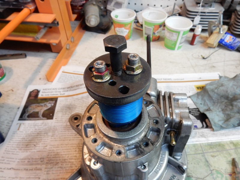
11. Remove the flywheel The Polini, Vittorazi, Minari and all others that use the IDM magneto have the same custom manufactured puller that MUST be used to remove the flywheel. The IDM flywheel on these engines has NO THREADED HOLES near the flywheel center that would permit an ordinary puller.
For other engines e.g., Top 80, an inexpensive puller from Harbor Freight works well.
If you do not have an impact wrench, use a chain wrench, a nylon strap, or oil filter tool to hold the clutch on the other end of the flywheel (if there is a clutch) in order to loosen the flywheel nut. If there is no clutch to grab, you may have to hold a pulley with a big adjustable wrench. It is not a good idea to push on the center of the crankshaft (unless the puller screw has a point). If the puller has a flat headed screw/bolt, thread the flywheel nut back on just a bit higher than the shaft so that the puller does not push against the threads. They are easily damaged!
REINSTALLATION: Installation of the flywheel on most engines is a simple job, but not on the Top 80 (and some others) which must have the ignition timed. Other engines have a keyed flywheel so retiming is not necessary. In any case, it is never a bad idea to check the timing, anyway.
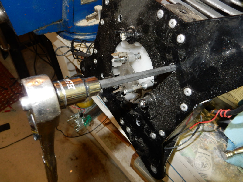
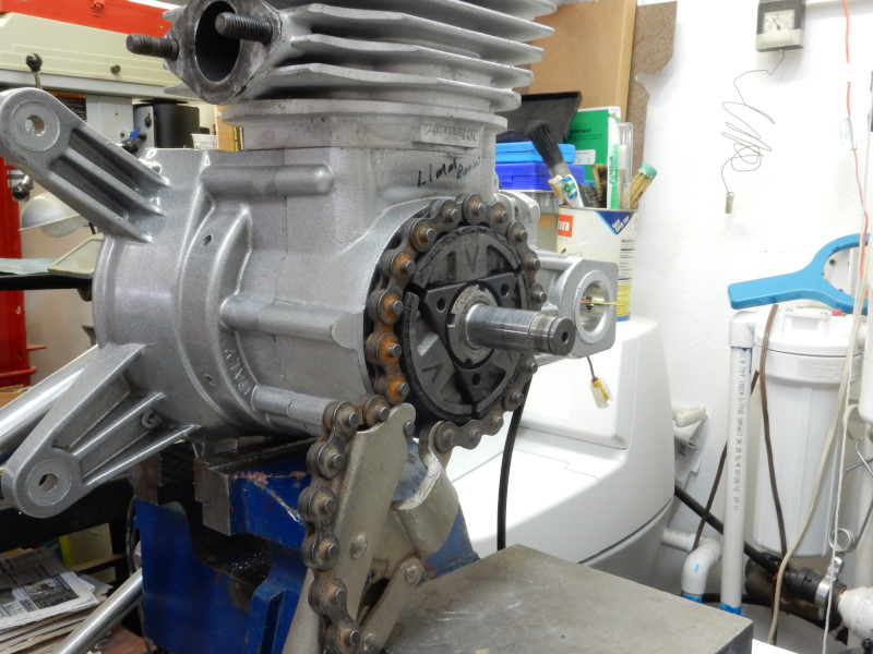
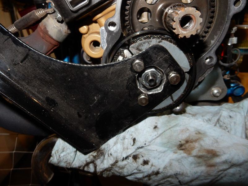
Sometimes, a chain wrench cannot be used to hold a flywheel while the flywheel nut is being removed, as here with the Minari. In this case, use nylon webbing from a ratcheting strap. Minari makes a special tool to hold the flywheel but webbing works better and will NOT suddenly come loose. If you have an impact wrench this procedure is an easy snap.
An ordinary wheel puller may be used to remove the Minari flywheel. The Minari special tool kit, however, also contains a puller to do this and is easier to use. You must have some means to hold the flywheel as you operate the puller. A chain wrench is the best tool but nylon webbing may be used if you do not have an impact wrench.

The Top 80 flywheel is easy to remove but you must have long 6mm bolts. The Top 80 finger-screws work perfectly. Be sure to put washers under the nuts on the finger screws or you will pull them right through most pullers.
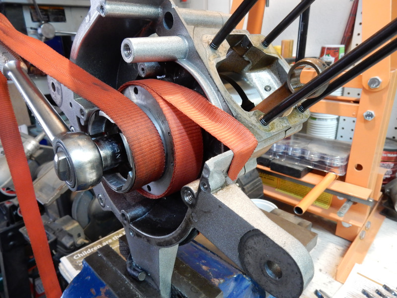
12. Remove the redrive or pulley from the crankshaft This task varies from engine to engine. An impact wrench is an important tool for removing nuts from crankshafts without having to secure the pulley or clutch. Without an impact wrench, you will have to purchase special tools that are unique for each make of engine. For aluminum pulleys, 60 seconds with a propane torch makes them come off much more easily, even just fall off.
REINSTALLATION: Make sure the clutch/drive pulley nut is torqued to specifications. The special tool to hold the clutch/drive pulley must be used when torque is applied. See below for the Polini reinstallation.
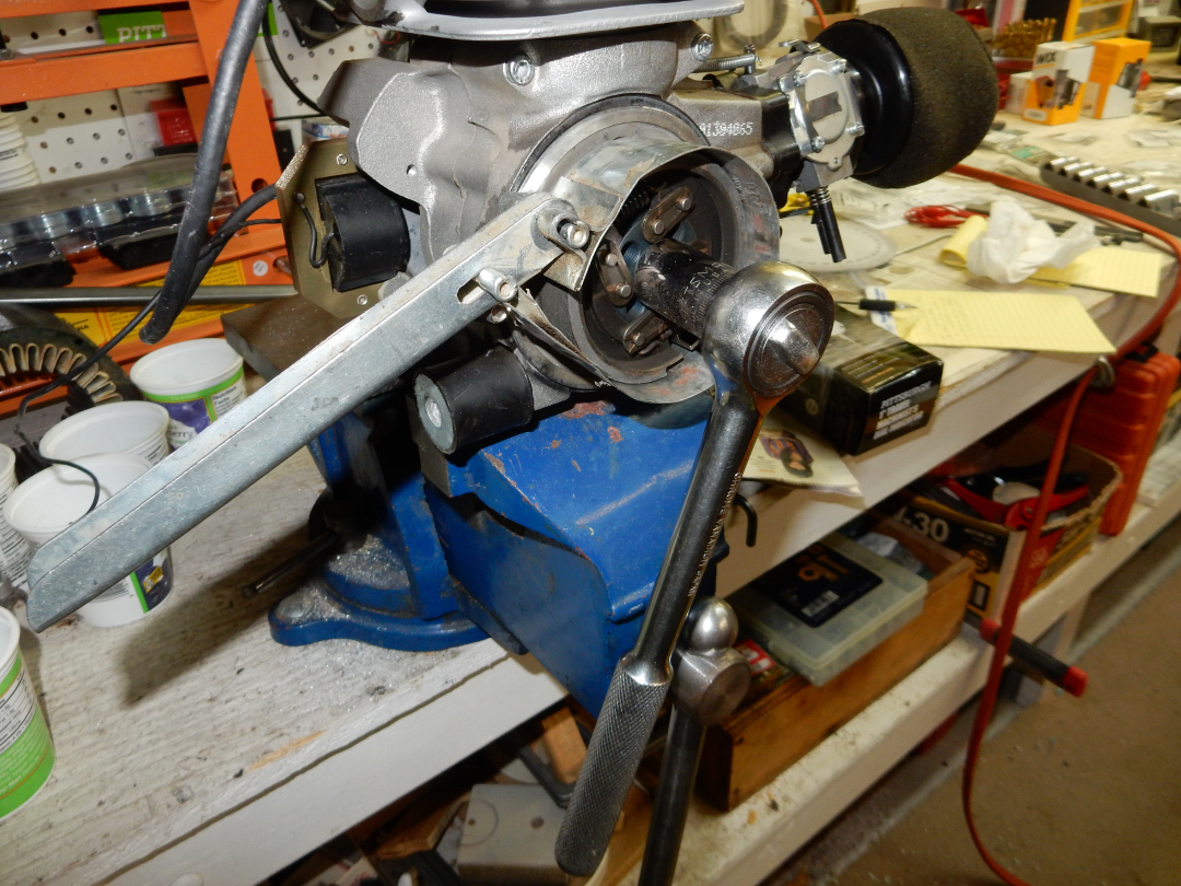
Removing the clutch nut on a Top 80. An oil filter wrench, nylon webbing, or a chain wrench (best) can be used to hold the clutch. Miniplane also makes a special tool that bolts to the clutch to hold it but using an oil filter wrench is much faster. Once again, an impact wrench makes this job a snap.
Holding a Minari clutch with a chain wrench. The grip on the object is immense but the chain wrench will not harm the surfaces because of the large surface area of the chain. Real tools, like a well-made chain wrench, are expensive and out of the domain of the Masters of Cheap (the Chinese). An impact wrench usually does not need anything to hold a pulley, flywheel, or clutch.
The shaft nut on the Minari is not an ordinary nut and requires a custom manufactured tool to remove it because it is recessed in the clutch and an ordinary shaft-nut spanner cannot be used. Note: The Minari spanner nut tool used to remove the clutch nut *MUST* have a 3-4mm shim between the tool and the 1/2" drive wrench. The tool will NOT grasp the spanner nut properly without it. Note: an impact wrench will break the teeth off the special tool. Do not use an impact wrench!
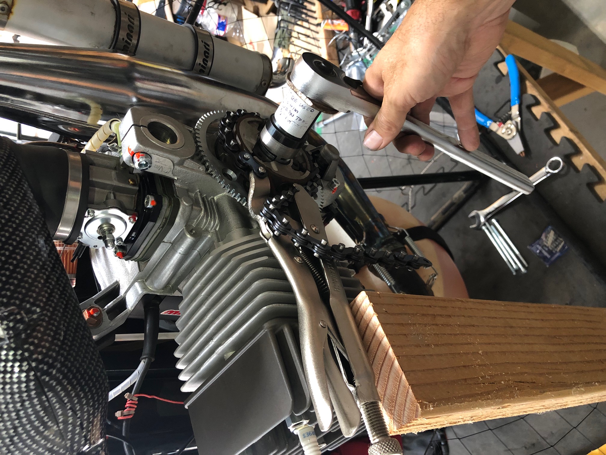
photo courtesy of Steve Jensen
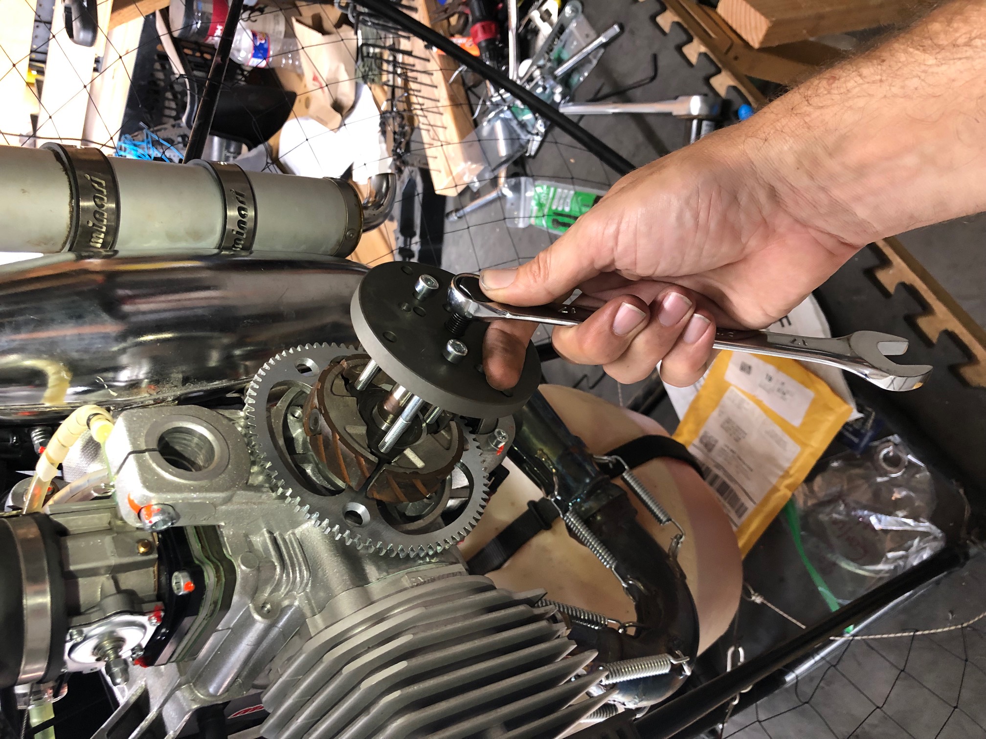
photo courtesy of Steve Jensen
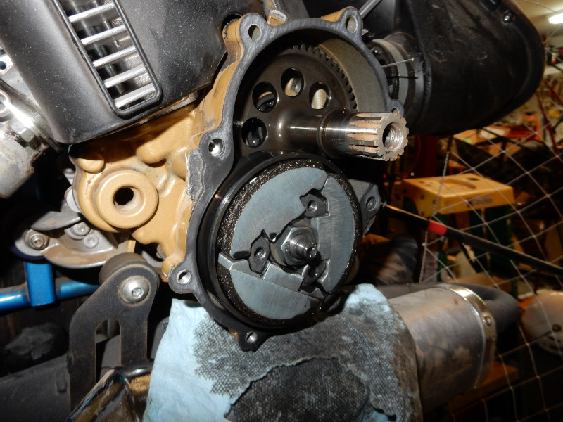
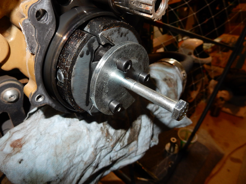
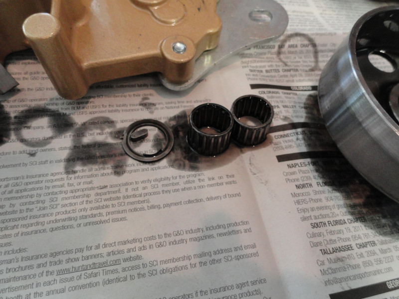
Ordinarily, the Minari clutch/drive pulley will slide right off the shaft after the circlip has been removed. In the engine below, the engine shaft was frozen/corroded to the (2) bearings inside the clutch/drive pulley. Sometimes, 60 seconds of heat to the exterior of the pulley will help things come off. It helped here. The pulley has no threaded hole with which to attach a wheel puller so this kind of puller (rarely used) had to be used instead.
Some Minari's have no clutch so the drive pulley requires a custom manufactured puller to remove it. Ordinary wheel pullers do not have the inner holes close enough to mate with the holes in the pulley. Heat aluminum drives pulleys to the temperature of boiling water in order to easily (and safely) remove them.
This engine (Minari) has a clutch and the Minari special tool can be used. However, an ordinary wheel puller may be used instead.
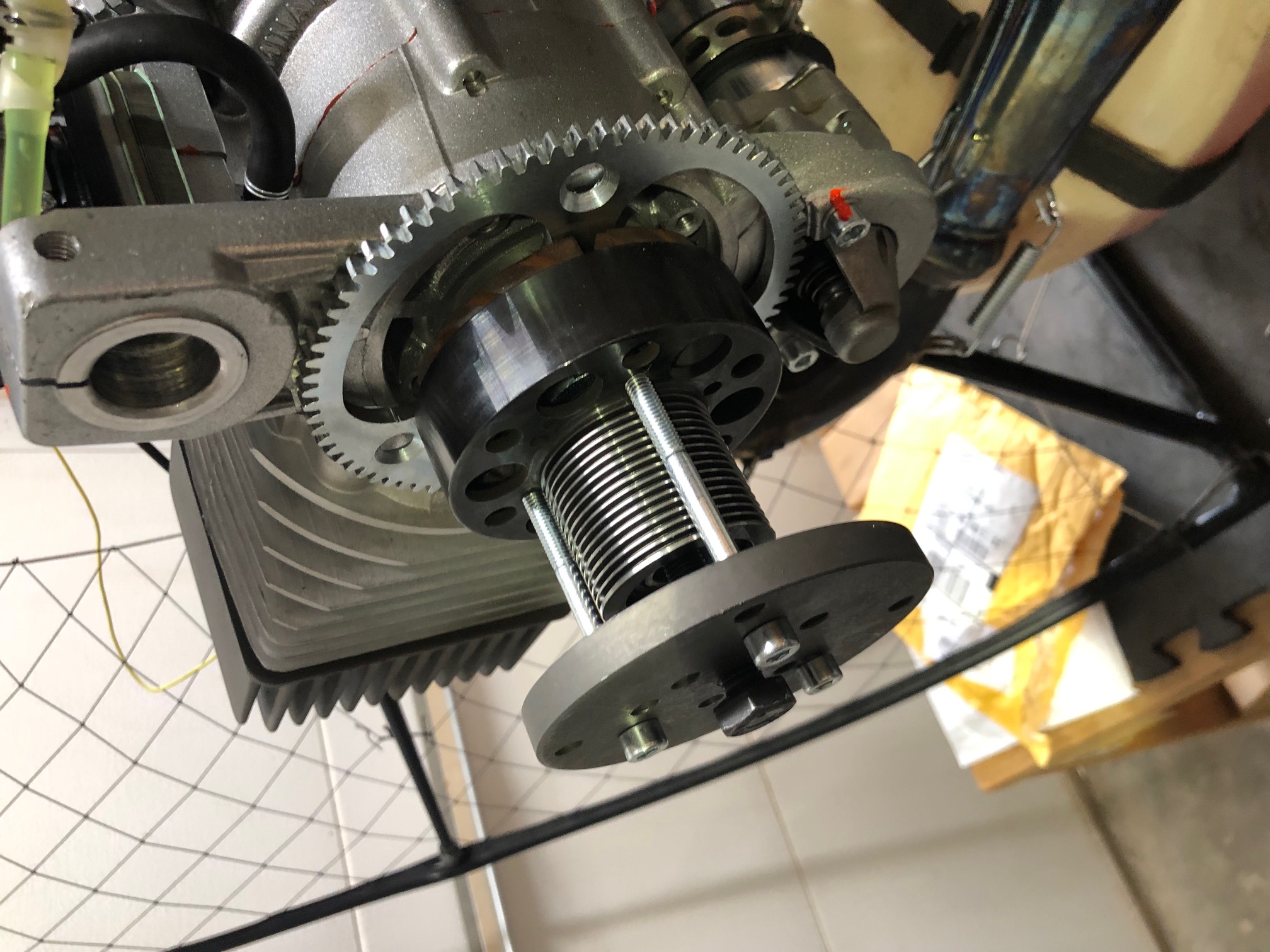
photo courtesy Steve Jensen
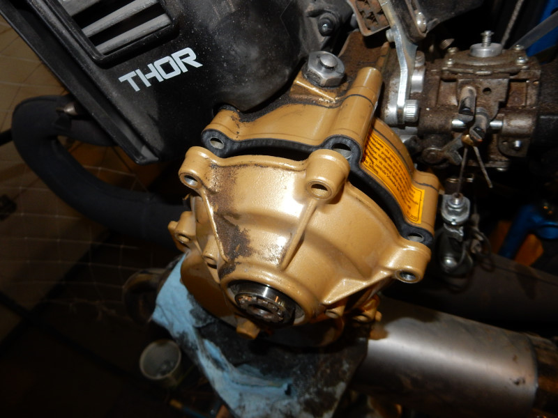
The Polini must have the propeller hub removed in order to remove the redrive/clutch assembly. The hub bolt has LEFT-HANDED threads and is removed in a clockwise direction.
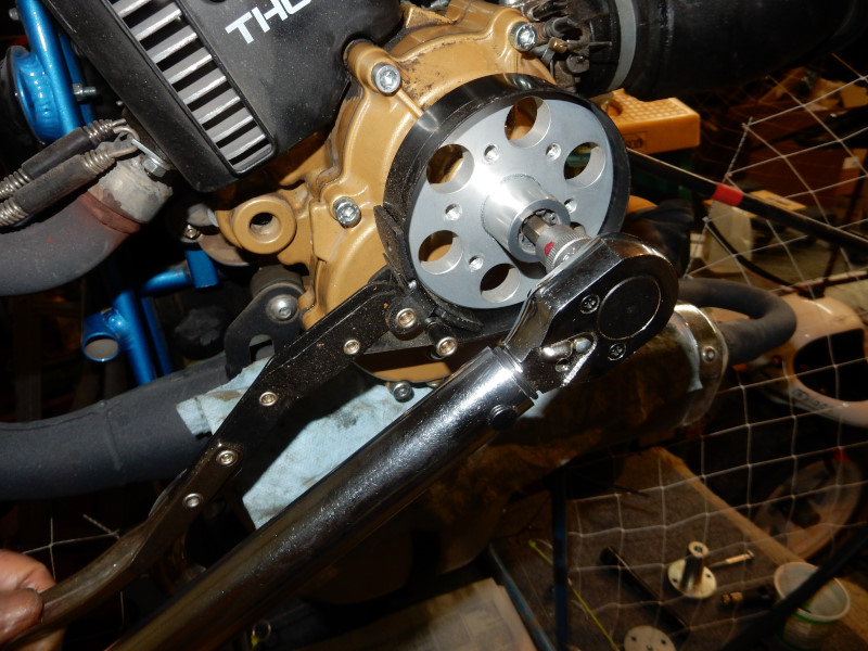
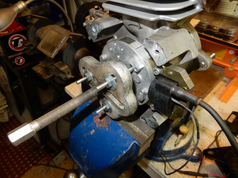
The Polini has a wet clutch. Remove the (7) cap screws, tap the outer housing a few times with a dead-blow hammer, and slide off the outer half of the clutch/redrive assembly. If the exterior rim of a pulley or hub is accessible, a quality oil filter wrench is the quickest way to secure it so nuts/bolts can be removed or installed. A chain wrench will also hold pulleys and hubs without damaging them but takes a few minutes to install it properly around the pulley/hub so the chain wrench will not damage nearby flanges and the like. Do not use an impact wrench to remove to the center screw.
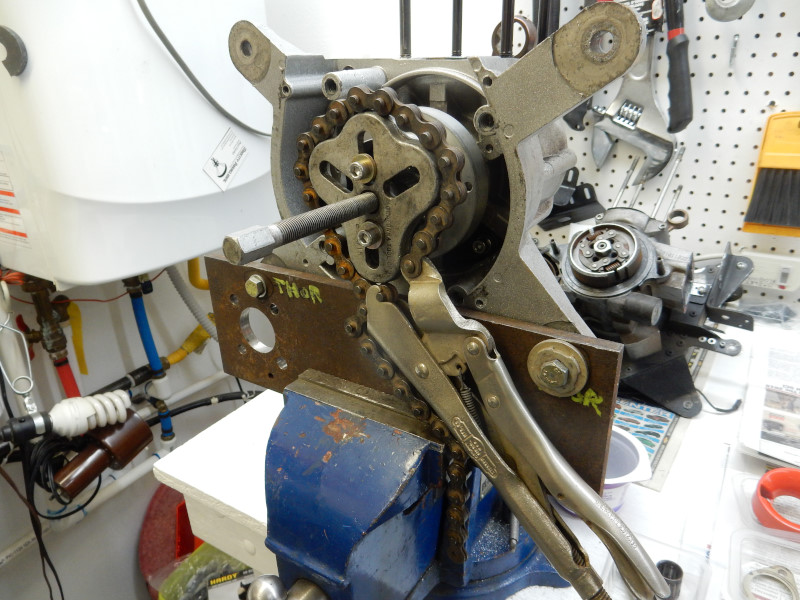
There has to be some way to hold the clutch from turning when removing the center nut. This tool is homemade from a thin piece of steel. A chain wrench or oil filter tool will not work. Polini has a similar specialized tool in their kit. However, an impact wrench will remove it easily without the special tool.
The Polini clutch puller is shown below but an ordinary wheel puller may be used, as well.
The Woodruff key must be removed for everything to slide off. Grab it with a quality set of pliers and gently wiggle it loose.
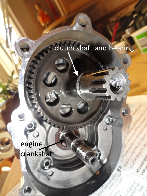
If the clutch shaft and bearing must be removed, it will have to wait until the case halves are separated. At that time, the shaft and bearing may be removed following the IMPORTANT INSTRUCTIONS on the bearing replacement page. Only a tool-monkey would even think of prying the shaft and bearing out. Don't be one.
For REINSTALLATION with the Polini: If the old gasket is still intact (not torn) it may be reused. The redrive casing bolts must be torqued in a cross pattern and incrementally. An impact wrench must not be used to re-install any bolts or nuts! A torque wrench and some manner of holding the rotating parts must be used.
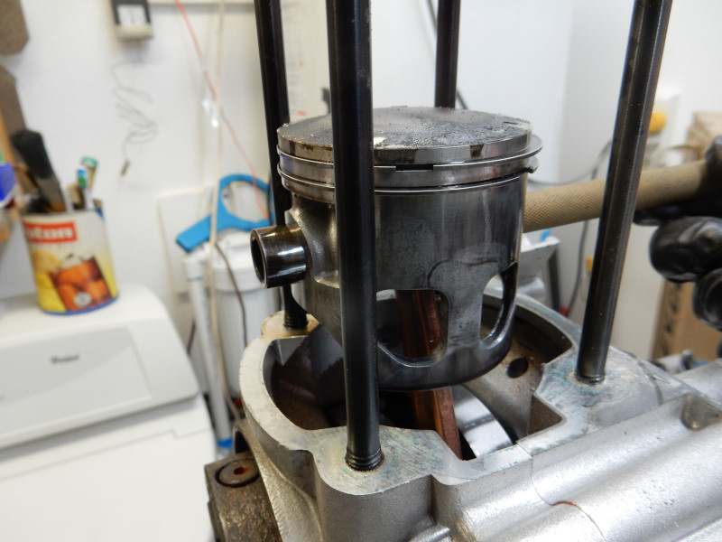
13. Remove the head and cylinder There are just (4) nuts on the top of the cylinder that hold the top end of the engine to the crankcase. Note the orientation of the gaskets. Some engines are specific as to which side of the gasket contacts a particular surface. If the cylinder is going to reused, be certain that the decompression port (if it has one) is clear. A clogged port will greatly shorten the life of the starter systems and may damage the top end of the engine due to increased compression.
Here is a photo of the upper parts of a connecting rod, the parts that connect it to the piston. In the U.S., the "gudgeon pin" is known as the "wrist pin" or "piston pin". These parts may be misnamed by parts suppliers e.g., "segment" for "wrist pin" due to translation issues.

Go to the piston ring page for how to check, remove and reinstall the rings.
Check that the honing pattern on the cylinder wall has not been worn off. It should look like this:
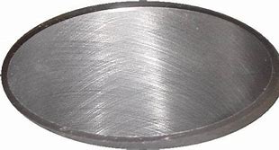
photo courtesy of Precision Surfacing Solutions
Generally, if any of the pattern is worn away, the cylinder should be replaced ($$$) or rehoned. Even a new piston ring cannot seal properly unless the honing pattern is intact.
Pilots can purchase a brush hone to rehone the cylinder wall if it not otherwise damaged (no scuff marks, scratches, or gouging). It is easy to use and the cost is much less than a new cylinder. Brush hones are superior than an ordinary cylinder hone because they maintain the existing shape of the cylinder and remove the least amount of material from the wall. Flex-Hone can supply the correct size brush hone, the proper cutting oil, and directions. We have had great success with the brush hone.
REINSTALLATION: (see the end of step# 14)
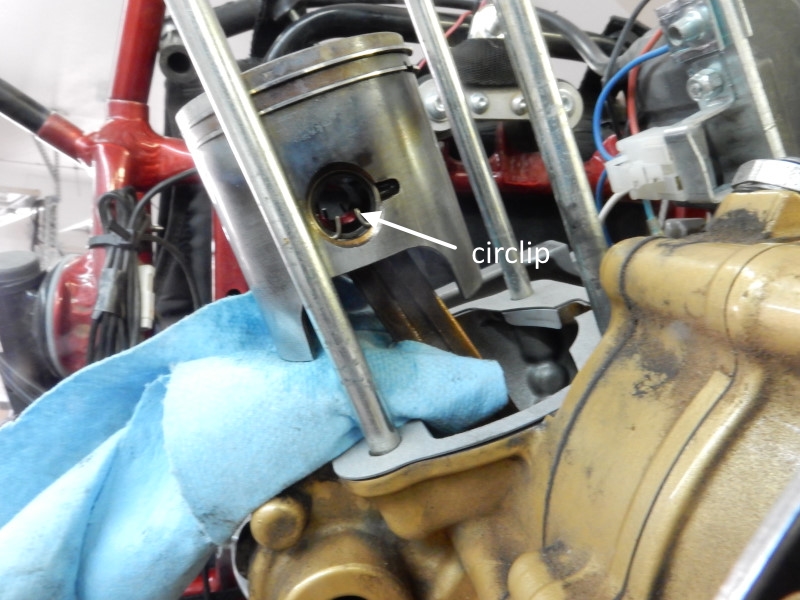
14. Removing the piston from the connecting rod Use a small screwdriver, pick, or pliers to pry out or grab, respectively, one of the circlips that hold the wrist pin in place. The Polini circlip has ears which make it easy to remove with a pair of needle-nosed pliers.
Use a hot air gun to heat the piston until a drop of water on the top of the piston sizzles. A brass drift, finger, or wooden dowel can be used to push the wrist pin out. The pin should slide out without any force. Some pistons may need to be heated with a torch if the clearances are particularly tight.
PISTON TO CONNECTING ROD REINSTALLATION: There is a small arrow on the top of the piston that *MUST* point to the exhaust port. Heat the piston with an air gun , as above, and slide in the wrist pin. Install the other circlip. If the circlip has ears (as in the photo below), use a pair of needle nosed pliers to make the circlip slightly smaller than the piston pin. DO NOT DEFORM THE CIRCLIP! The Top 80 does not have ears so a small screwdriver must be used to work the circlip into the piston. Orient the piston properly and then install a circlip in the side of the piston that faces the front of the engine.
After the circlip is installed, turn the engine upside down and and apply a few drops of 2 stroke oil to lubricate the upper connecting rod bearing.
PISTON RING REINSTALLATION: see the Piston Rings page for how to do this.
CYLINDER AND HEAD REINSTALLATION: Note whether your engine requires the squish to be measured and the correct sized cylinder gasket to be used. Install the cylinder gasket. There is a special pin in the piston land to ensure that the piston ring is in the correct position. If the ring is not oriented to the pin, the ring will not compress completely and the piston will NOT go into the cylinder. Oil the sides of the piston and use your finger to smear oil around the inside of the cylinder. Use your fingers to squeeze the tips of the ring(s) together and push the piston into the cylinder. As you squeeze the ring together, you can rotate the ring so that the pin is directly under the gap in the ring. Use a new cylinder head gasket and install the head. Torque the head nuts to specifications in a cross pattern.
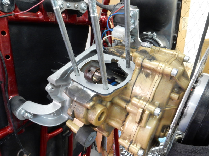
15. Splitting the crank case Remove all of the case bolts then split the case halves using the special tool. Be sure to follow the directions that came with the tool.
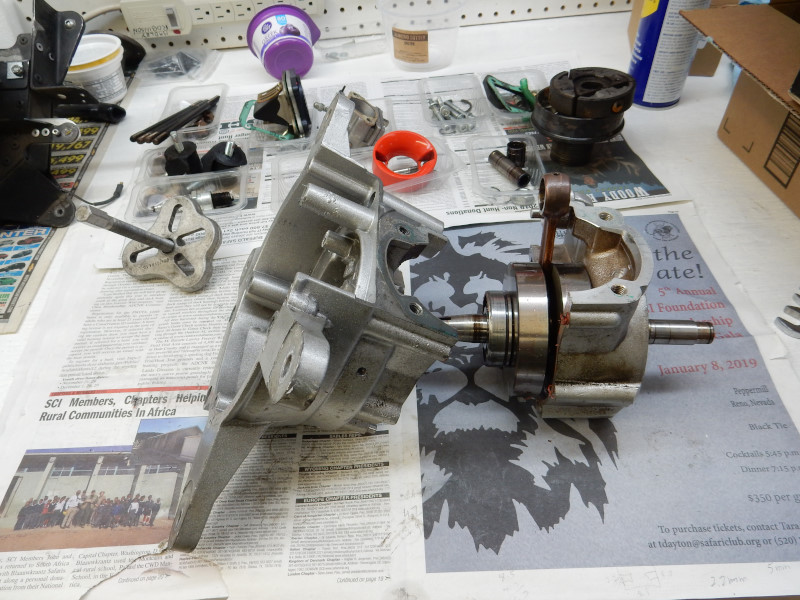
All paramotor crankcases are split the same way, just like a motorcycle crankcase but a lot easier and simpler. As often as not, there are complications when splitting a crankcase, especially if the engine is more than a few years old. The Minari shown here was run in a marine environment which is the absolute worst environment for any engine. Pilots should store their engines in an air conditioned space to minimize corrosion.
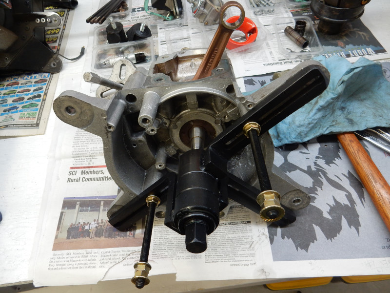
The crankcase splitter tool is bolted to one of the halves and then it pushes the crankshaft through the bearing on that half. The crankshaft pushes against the bearing on the other half and forces the two halves apart. Note: Always be sure to put a nut on the end of any threaded shafts being pressed out in order to protect the threads.
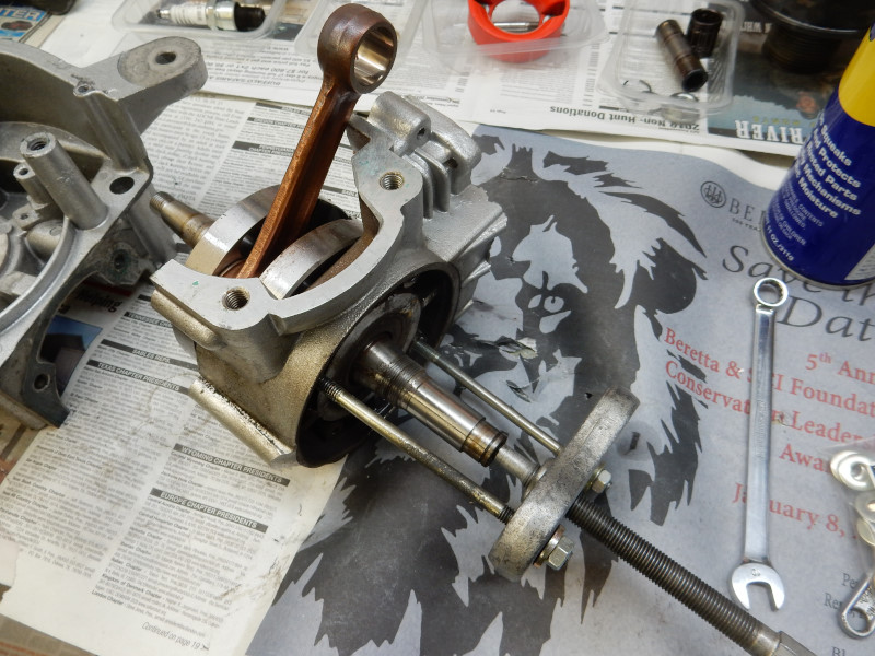
When you just start using the tool, carefully observe the bearing in the case half that the tool is connected to. If the crankshaft is moving through the bearing, all is good. If the bearing is frozen to the crankshaft, as in this engine, you will see the bearing start to move out of the bore in the case half.
STOP!
You must now apply heat around the bore of the bearing with a propane torch (an oxyacetylene torch may quickly overheat the aluminum and ruin it). Using the propane torch, heat the bore to about 180ºC (356ºF). You must have an infrared temperature gauge to do this. Do not exceed 190ºC (380ºF) or the case half may be ruined. Heat things slowly while monitoring the temperature. Once the temperature is correct, the bearing should easily slip out of the bore as the case halves are separated with the tool. If you do not heat the bore, continuing to press out the bearing may ruin the bore i.e., as you force the bearing out of the bore, the bearing may take some of the bore material (aluminum) with it. The bore will now be oversized and when the bearing is replaced, it will be loose in the bore. If this happens, the crankcase halves must be replaced.
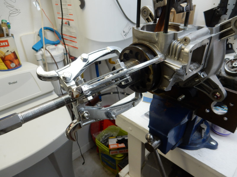
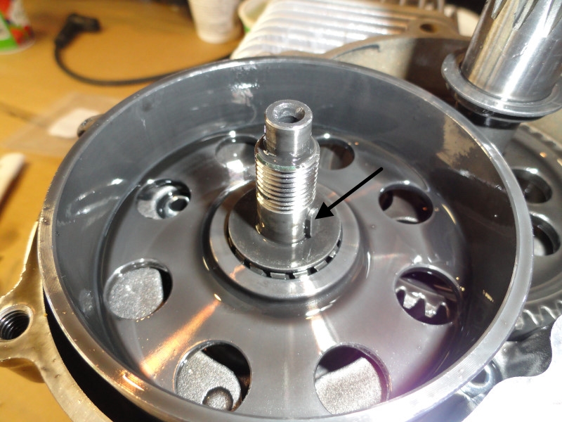
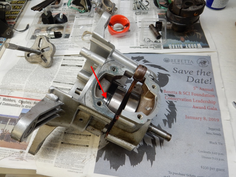
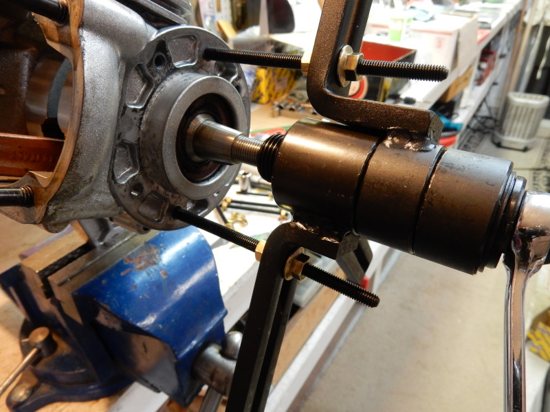
Once the crankcase is split just a little, it should be easy to use a dead-blow hammer to tap the shaft the rest of the way out. This motor had one of the main bearings frozen on the crankshaft (red arrow).
The crankcase splitter or an ordinary wheel puller may be used to push the crankshaft out from the other half.
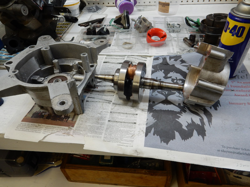
The crankshaft is completely removed from the halves. Bearings frozen on a shaft should be removed with a crank bearing/gear puller.
DO NOT REUSE BEARINGS REMOVED WITH THIS TOOL!
This tool puts extreme forces on the bearing race and it will likely be damaged in the process.
The inner race of the bearing was heated to a blue color with a propane torch and was able to be pulled off. The bearing was ruined and had to be replaced. An oxyacetylene torch is better in this situation than a propane torch because it heats the bearing up much more quickly and, consequently, it will expand faster than the shaft.
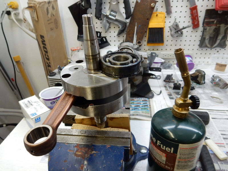
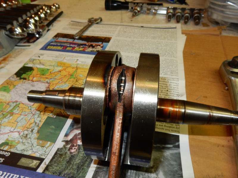
The engine below had badly overheated. It got so hot that the lower rod bearing had begun to seize. The steel face of the counterweight was scorched from the friction and the bronze thrust washers had begun to melt. The pilot had misadjusted the carburetor. It was an expensive mistake.
When an engine is completely disassembled, it is common to find parts frozen together. This is where the use of heat is critical in order to prevent damage. Most pilots should use a propane torch with an infared temperature gauge. This will ensure that parts are NOT overheated.
16. Bearing removal Follow the instructions on the bearing replacement page. NEVER BANG OR PRESS A BEARING IN/OUT OF A CASE HALF!
REINSTALLATION: Follow the installation instructions on the bearing replacement page above after seal installation.
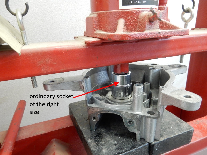
17. Oil seal removal Remove with a press and the correct sized pipe/socket/drift. The drift must just clear the opening in the case.
REINSTALLATION: Follow the installation instructions on the bearing replacement page which includes reinstalling the crankshaft and assembling the case halves together.
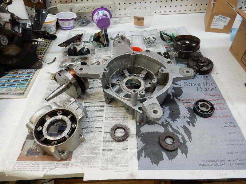
18. Clean & examine the engine Once the engine is completely disassembled in must be thoroughly examined and cleaned with mineral spirits and compressed air. When an engine is disassembled to this extent, it is always a good idea to replace the main and clutch bearings and all seals. In any case, follow the maintenance intervals given for your particular engine. In general, 300-400 hours is the time when a major overhaul should be performed. If you wait until the engine fails, you will have a much more expensive repair.
19. Reassembly of the engine is the reverse It is a good idea to record the default compression of the engine when it is rebuilt/new. With this information, it is easier to know when a top end rebuild is necessary.
![]()