


Bearing & seal removal, replacement, case assembly in 2 stroke paramotors
by Had Robinson
updated December 31, 2025
As many motorcycle and kart racing sites warn, bearings in aluminum cases must be removed carefully. Small cases may be heated with a torch but it is not nearly as precise as heating the case in an ordinary oven. Using a press or a hammer and chisel to remove a bearing from an aluminum case can ruin the bore that the bearing sits in. This is because the bearing must have a tight fit and pressing a bearing that is tightly fitted into a soft aluminum bore will enlarge/damage the bore. This procedure assumes that you have intermediate mechanical skills. Do not attempt this project unless you have the special tools listed here.
A. Special tools needed for bearing removal and installation
When things are badly frozen/corroded on shafts, more complex (and expensive) tools are required.
- propane or oxy-acetylene torch
- oven – an ordinary kitchen oven or toaster oven may be used, depending on the size of the case halves.
- infrared laser thermometer (available from Harbor Freight)
- blind bearing removal tool – available on eBay from various sources. The Tusk brand is the best. It has more collets but costs more. Regardless of the tool used,
it must be used correctly. The tool used to remove bearings
must first have the collet FIRMLY set inside the bearing. The collet should be tightened with wrenches. DO NOT OPERATE THE SLIDE IF ANYTHING IS LOOSE.
The YouTube videos of blind bearing removal
are made by amateurs who do not know how to correctly use these tools.
- hydraulic press – a 20 ton press is, by far, the best to use and is an important investment for any pilot who regularly works on an engine. If size is a problem, a small press may be used but there may a problem due to a lack of working space around the press area. In a pinch, a big vise may work.
- crankshaft puller – this tool is used to pull the crankshaft into the bearings. A press may be used instead but this tool makes it safer and easier to seat the crankshaft into the bearings. The link is for the Harbor Freight tool but Tusk makes a better one.
B. Splitting the case
See splitting the crankcase on the "Rebuilding a paramotor" page for instructions. It requires a special tool.
C. Bearing removal
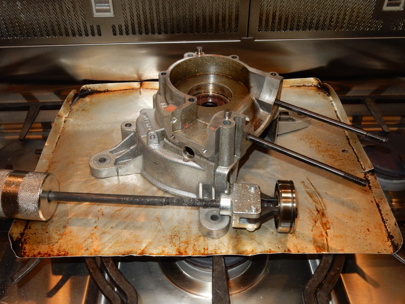
1. Heat the case half
Before removing the bearing, preheat the oven to 190ºC (380ºF). Note: When aluminum parts are heated to 205ºC (400ºF) or more, the metallurgical properties of the aluminum are affected which can ruin the case half.There must be a flat surface between the heating element/burner and the case half like a cookie sheet or a piece of cast iron (best). Place a couple of thin steel rods (tent stakes work) on the flat surface so that they can support the case half. This will allow the case half to heat up more evenly. Put the case half on top of the rods with the bearing facing down.
Use the infrared temperature gun to monitor the temperature of the case half every 3 or 4 minutes while it is being heated.
2. Remove the bearings
When the bore of case half reaches around 160ºC (320ºF), the bearing should simply drop out a make "click" sound. Remember to be extremely careful NOT to heat the case half more than 205ºC (400ºF)!
If the bearing is still in the bore when the bore surface reaches the correct temperature, heat the bore to 170ºC (338ºF). Then remove the case and let it drop a few inches on a semi-hard surface. The heated case cools quickly so work must be done fast.
If it still does not drop out, quickly use the bearing removal tool to remove it but this should be rare. If there are still problems, heat the case to 188ºC (370ºF) and try again with the tool. It is better to heat the case half a little hotter rather than risk injuring the bore.
The bearing in one case half of this engine required the bearing removal tool to remove. It only took one very light tap of the slide to remove the bearing. The bearing in the other case half fell out when the correct temperature was reached.
3. Evaluate the bearings
To test the existing bearing clearances and determine if there might be any damage, use compressed air (fine tip) on the balls of the bearing (video here). If the balls and the inner race move freely with air, all is good to go. In the video, the bearing on the left freely rotates but not the bearing on the right, even after it was cleaned. Generally, it is best to replace the main bearings when replacing the crankshaft.
Rarely, the bearing may be clean yet may not turn freely, as in the above video. This bearing was defective and cannot be used. These bearings have tremendous loads on them, get hot, and spin up to or exceed 9,000 RPM. If the bearing is already binding in some way, it will bind all the more once it heats up and may even freeze, ruining the crankcase.
Note: This test will not work for sealed bearings e.g. the ones in the clutch on some engines. These bearings are not subjected to the kinds of temperatures and loads that the main bearings are. However, I have noticed that the Italian manufacturers have not used quality bearings in some of their assemblies.
4. Remove the seal
The seals are removed after the bearings because it is much easier. Before the case completely cools, remove the seal. The seals do not fit as tightly as the bearing and can be pressed out using a drift. A large socket can be used that is just narrower than the inside rim of the seal to press it in. For example, the inside dimension of a Minari main seal is about 43mm. The outside diameter of a 1 1/4" socket is just under 42mm. The socket will push on the bottom of the seal. A press should be used to push against the socket and then against the seal. Be sure to examine the old seal carefully for any modifications needed that will allow oil to enter the closed space between the bearing and the seal. If OEM seals are purchased, they will come with the proper modifications.
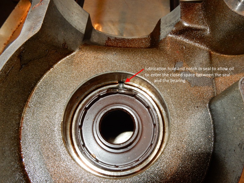
The main bearing seal below had been modified AFTER it was installed in the bore by placing the bit in the lubrication hole and cutting the notch visible in the photo here.
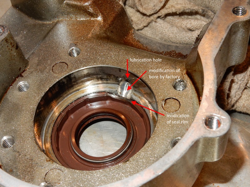
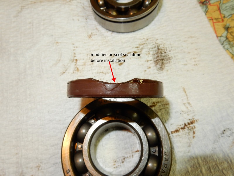
The seal in this case half was modified BEFORE installation. The lubrication hole was modified by the factory to allow oil to enter the closed space.
D. Installation of the bearings and seals
For more information on how to do this procedure, go to this site by MicroBlue Bearings. Information from their site was used here. We thank them for their help.
WARNING: The bores for main bearings have lubrication holes. BE CERTAIN THAT THE OIL SEAL DOES NOT COVER THESE HOLES.
Preheat the oven to 190ºC (380ºF).
The new bearings usually have grease or heavy oil on them and be thoroughly cleaned. Use brake cleaner or pure gasoline to remove every trace of oil/grease and compressed air to dry/remove any residue. Use the bearing test procedure given above (C.3) to be certain that the bearings are good.
DO NOT INSTALL MAIN BEARINGS THAT ARE NOT PERFECTLY CLEAN!
1. Freeze the bearings
Insert the blind bearing removal tool collet into one of the bearings. Tigten by hand ONLY. Having the collet inserted in the bearing helps align it when dropping it into the bore. Place the bearings in a cold freezer for an hour.
2. Prep the seals and case halves
Depending on the engine, a special cut in the seal's rim may need to be done so that it will not cover up the lubrication hole. If the seals are not modified, use a Dremel-type tool. If the cut was already made or must be done after the seal is installed, skip this step.
Clean the case halves thoroughly, especially the bores. It is easy to become confused which is the interior and exterior of the case. With a felt tip marker, make an "E" on the exterior side of the case next to the bore. This will help to make sure that the exterior side of the seal faces the exterior of the case half.
3. Heat the case
Heat the case in an oven until the area of the bore is about 177ºC (350ºF). Use an infrared gun to measure this temperature.
4. Insert the bearings
The next step is always the most difficult! Review what needs to done, have the right tools available and set, follow the steps below exactly. Remember that the case halves must be the right temperature! Have the rest of the bearing tool handy in case you have to remove a jammed bearing that was put in crooked.
Remember to work QUICKLY.
Remove the bearing with collet installed from the freezer. With the bearing in one hand, remove the case half from the oven with the other hand, align the bearing with the bore, and let the bearing drop in. The collet can be allowed to drop on the bearing. The bearing should go in easily. Make sure the bearing is fully into the bore by observing the rim of the bearing. It should be perfectly even around the rim of the bore. Wait a minute or two, loosen the collet, put a hot pad on one side of the bearing, and pull the collet out. Putting some pressure on the bearing ensures that it will not be inadvertently pulled out with the collet.
If the bearing gets crooked while inserting it into the bore, the slide must be quickly attached to the collet and
the bearing removed ASAP. It may be necessary to remove the partially inserted bearing per the removal section above.
The aluminum bore cools very quickly and grabs the bearing tightly. The slide hammer should just barely be tapped so that
minimum stress will be put on the aluminum bore and case.
Never hit a
bearing in with a tool! This can jam the bearing and ruin the bore. If the bearing does not nicely drop into the hole, the case is not at the right temperature. If necessary, repeat the
process starting with step #3. Put the bearing back in the freezer.
Once the bearing is in place, move the case with the bore opening facing up to a safe place where it can cool slowly to room temperature. If the case half is anything other than in a horizontal position, it is possible for the bearing to slip out a fraction or fall completely out.
5. Install the seals
If the seals are modified, mark the modified area and the lubrication holes in the case halves so that they are aligned.
Use the press or a vise and an OVERSIZED socket/drift to install the seals flush with the rim in the case. The oversized socket/drift will ensure that the seal is not driven too far into the case half. If you use a dead-blow hammer to pound the seal in, make certain the seal goes in square. Be careful because it is easy to ruin the seal. Never use an ordinary hammer to pound anything on a an engine.
6. Assembling the case halves
Be certain to check the lubrication holes before assembling the case halves. They must be 100% clear and open to the seal and bearings.
Before sliding the crankshaft into the case halves, put petroleum jelly (Vaseline) around the inside surface of each seal and on the crankshaft where it contacts the seals. This will insure that the seals are not dry. If they are, they will quickly be destroyed when the engine is first started.
It is uncommon that the shafts will slide right into the bearings on each case half easily. Make sure any dowel pins are in place so that the case halves are exactly centered.
The most difficult task when re-assembling case halves is NOT to use too much RTV sealant. Too much RTV sealant will form beads on the inside of the crankcase, eventually break off and, find their way into the main bearing lubrication holes. The clogged holes will prevent oil from reaching the bearings and, more importantly, the seals. The net result is that the seals fail and the lives of the bearings are shortened.
Here are photos of a Top 80 crankcase where the pilot overdid the RTV on the halves. Already, pieces of sealant are loose in the crankcase and will eventually find their way into the small holes that provide lubricating oil for the bearings and seals.
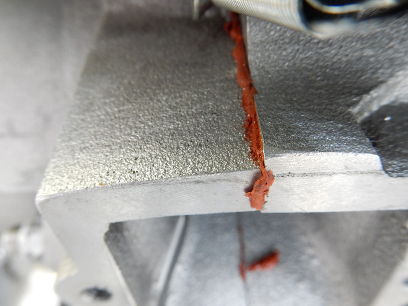
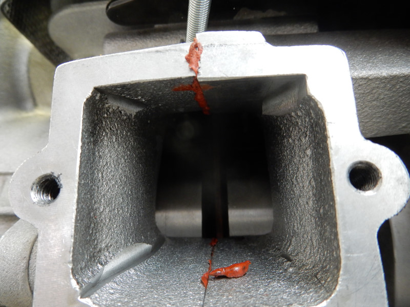
It is difficult to fix this mistake The cylinder must be removed. A piece of cloth will have to be jammed into the area just below the lower connecting rod bearing and the crankshaft turned back and forth to loosen and remove the excessive sealant which lies in the joint surrounding the crankshaft. For other parts of the joint which are exposed, it is easy to remove the excessive sealant. Compressed air will have to used to blow out and pieces that remain. This engine was not run so it is very unlikely that any bits of sealant are already in the bearing lubrication holes. On the other hand, this engine could be put into service and the pilot can just hope for the best.
Make sure which end of the crankshaft goes in which case half! Use a felt tipped marker to write on the shaft. It is embarrassing to put the crankshaft in backwards.
Using the crankshaft puller tool – Smaller engines, like the Top 80. have a smaller threaded crankshaft than the bigger engines which requires a smaller nut rather than the stock nuts which come with the puller. In this case, use the actual shaft nut and a thick washer when using the puller on smaller engines. Center the puller over the case half in order to pull as straight as possible. Some way of preventing the puller from turning as the nut on the end of the tool is tightened may be required e.g., a chain wrench. WHILE PULLING THE CRANKSHAFT INTO THE BEARING, KEEP THE CONNECTING ROD ORIENTED INLINE WITH THE CYLINDER PART OF THE CASE HALVES. If this is not done, the connecting rod will be jammed into the sealing edge of the case half.
Using the tool, pull the drive pulley/redrive end of the crankshaft into the drive pulley/redrive case half.
As the shaft is pulled home, the center of the upper connecting rod should line up with the edge of the case half. Most connecting rods have a lubricating hole at the center of the top of the rod which can help tell when the shaft has been pulled home.
Now, we need to pull the flywheel side of the crankshaft through the bearing in the 2nd case half. Make sure all of the bolts that hold the case together have been cleaned and are handy.
With nitrile gloves, apply a thin amount of RTV sealant to the other case half.
Slide the case half onto the flywheel side of the crankshaft and attache the crankshaft puller with the appropriate nut and, if needed, a washer. Pull the shaft through the bearing in the same manner as was done with the first case half. As the shaft is pulled, line up the centering pin/collars. Just before the pins/collers touch the other case half, insert and hand tighten the case screws.
Continue pulling on the crankshaft alternating with a hand tightening of the case screws. When the two halves come together and a bead of RTV is formed between the halves, stop the pull and remove the puller. Continuing to pull the crankshaft after the halves have come together and formed a RTV bead will load the bearings and cause them to fail prematurely.
Remove the crankshaft puller. The crankshaft should turn freely and well as have some lateral movement. To check for lateral movement, grasp one end of the crankshaft and pull it back and forth. There should be some detectable movement. If there is no movement, take a plastic headed hammer and strongly strike each end of the crankshaft 6-10 times. Test again for lateral movement. Repeat this until lateral proceure is detected.
The case screws can now be tightend to the specified torque in a cross pattern.
Check again that the crankshaft turns freely by hand. Finally, take a plastic headed hammer and again strike each end of the crankshaft 6-10 times. This will help ensure that there is no lateral load on the bearings.
Put copious amounts of 2 stroke oil on the main and lower connecting rod bearings. Make sure some goes down the lubrication holes in the crankcase. The engine is now ready for further reassembly.
![]()