External pulse port for paramotors
by Had Robinson
updated November 25, 2021
Most paramotors have an external pulse port (PP) on the crankcase but not all, including the Top 80. The PP is a passageway (internal or external) that connects the crankcase with the carburetor fuel pump. The pulse waves generated in the crankcase are used to power the pump. The Top 80 has an internal PP that goes from the crankcase, through the reed valve body, and then to a small hole on the engine-side face of the carburetor. This small hole is connected to the fuel pump inside the carburetor.
What is the need for an external PP on the Top 80? An external pulse port has a larger diameter which better transmits the pulses to the pump. This is why most paramotors have an external PP and carburetors with an external PP fitting. Also, an external PP can drive an auxiliary fuel pump (used with the FSM) or another pulse driven accessory. When an engine is operated in very cold or very hot conditions there are more problems with fuel delivery and the need for an auxiliary fuel pump.
Modest mechanical skills are needed to drill and tap a hole in the Top 80 crankcase. There are a number of online videos which can help if you have never made threads on anything, especially in aluminum. The metric equivalent of the 1/4" barb is the 6mm barb, though the latter does not come with a sealing O ring. If a metric barb is used, the appropriate metric drill and tap must be used.
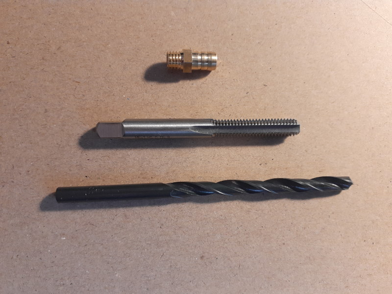
Special tools and parts needed
The adapter, tap, and drill bit may be ordered here as a kit - FREE shipping (continental U.S. only)
- 6mm barb male adapter
- M6 x 1mm tap – a 6mm counterbore is unnecessary because we are dealing with low pressure and the barbed fitting does not have to be perfectly flush with the surface.
- 5.0mm bit (hole size for the tap)
- RectorSeal #5 pipe thread sealant – available in hardware stores (do *not* use Teflon tape)
- thread cutting oil – almost every hardware store will have it for threading steel pipe. Aluminum tends to gall and and this special oil helps prevent this. If you cannot find it, mix some diesel or kerosene 50-50 with chainsaw bar oil.
- center punch – optional but recommended
- spray brake cleaner – available from any auto parts store

Steps
The following is for the Top 80, other engines are similar.
- Remove the air box and carburetor. You can let the carburetor safely hang by the throttle cable
- Remove the reed valve body
- Remove the redrive (it is in the way)
- Mark a spot with a felt-tipped pen on the side of the crankcase 12mm (1/2") from the top and 16mm (5/8")
from the reed valve cavity in the crankcase. The photo below
shows the approximate location of where the external pulse port should be located. The location does not have to be precise.
In fact, it could be on the top or another side of the reed valve cavity. Using a center punch and a hammer, make an indent where you will drill the hole
which will keep the drill bit from "wandering" as you begin to drill.
The port can also be installed near the bottom of the reed valve cavity. The important concern is that the new port opening on
the inside of the crankcase clears the reed
valve by 6mm (1/4") or so. The threaded part of the adapter is short and will not intrude into the crankcase so it can
be installed in the most convenient location. If you make a mistake, it is easy to put an M6 brass plug or even JB Weld epoxy
putty in the hole and try another area. Remember that there is never any high pressure in the crankcase.
- Tilt the reed valve cavity down so that the cutting oil and other fluids can run out of the cavity and
*not* into the crankcase. Stuff a clean paper-towel or rag tightly into the cavity, right up against the crankshaft. You want to prevent stray aluminum chips
(scarf) from getting into the crankcase. For extra safety, use some brake cleaner or mineral spirits to clean the inside of the
crankcase where the new hole will be and put a bit square of duct tape over the inside area where the hole
will exit into the crankcase.
When the drill bit enters the cavity, it will push the tape a little (if you are careful) and *catch* the chips. The paper-towel
or rag should be stuffed far enough in to clear the new hole. Also, put a piece of duct tape, sticky side up, on the
bottom part of the cavity to catch
any scarf (aluminum shavings) that falls out of the new hole. The duct tape will save work after you finish drilling the hole.
- Use the 5.0mm bit to cut the hole for the tap. (If you have never drilled and tapped a hole before,
you might want to practice first on a piece of aluminum stock you can purchase from a hardware store.) Put plenty of cutting oil on
the bit. The hole must be perpendicular to the outside surface of the crankcase. (This DIY video
is helpful even though a drill press is used. It shows a hole being cut and threaded in aluminum.)
Run the drill 300-400 RPM. Push firmly on the bit when making the hole. Drill a few seconds, withdraw the bit, and put some cutting oil in the
new hole. Repeat this process until the hole
is through the crankcase. The oil will help the chips eject from the hole while the bit is cutting. If the resistance on the drill starts to increase, back out immediately,
while keeping the bit slowly
turning. If you completely stop the bit from turning, it could jam. Make sure there is always plenty of cutting oil in the hole while drilling.
- Tap the hole. If you do not have a T-handle to hold the tap, use a small adjustable wrench to turn
the tap. Push the tap into the hole, coat the cutting surfaces with cutting oil, and gently turn it
a few turns to begin the threads. Cutting oil must be used, not ordinary
oil. If cutting oil is not used, the aluminum chips may seize the tap and gall the new threads. Once the tap
begins to cut deeply, turn the tap an additional half turn, back it out a half turn, then back in one full turn. Going in and
out helps ensure that the scarf is removed from the hole. Remove the tap after
each complete turn and remove the chips with air or a toothbrush. Take your time if you are new to this sort of thing.
- With the reed valve cavity still tilted down, clean any scarf from the new hole with air
or WD-40. After the hole is 100% free of scarf, use brake cleaner to clean the
threaded hole of any traces of cutting oil. It is better to spray the brake cleaner into the hole from the inside of the cavity.
The brake cleaner removes traces of oil but we want to be sure it does not run into the crankcase.
Now use brake cleaner to clean the cavity of all traces of oil and chips. When done, pull out the paper-towel that protected the crankshaft.
IT IS IMPORTANT NOT TO LEAVE ANY METAL DEBRIS INSIDE THE CRANKCASE!
- Install the male adapter. Coat the threads with the RectorSeal and screw it in. Do not use use Teflon tape as it can get loose and clog the
small holes in the crankcase that bring oil to the
main bearings. Use a 7mm socket and tighten the adapter to 7 in lbs. (0.9 Nm) or just snug. The photo below shows the 6mm pulse port
in an alternate location because I had installed a different sized port
earlier. If you make a mistake, such as cutting the hole too big or stripping the aluminum threads,
J-B Weld epoxy putty can be used to permanently attach the adapter. If you have to use it,
be sure there are no traces of anything in the hole or on the adapter. I have used this putty to repair damaged holes in engine
blocks. It is very high quality.
- Re-assembly is the reverse. When installing the reed valve body, follow the directions given in step #5 on the reed valve page. Do not over-tighten the nuts holding the carburetor and air box onto the engine. See the Top 80 specs page for torque help, if needed.
![]()


