


Magneto ignition systems
by Had Robinson
updated December 15, 2024
Italian paramotors with magneto ignition systems are all made by the Italian company IDM.
How they work
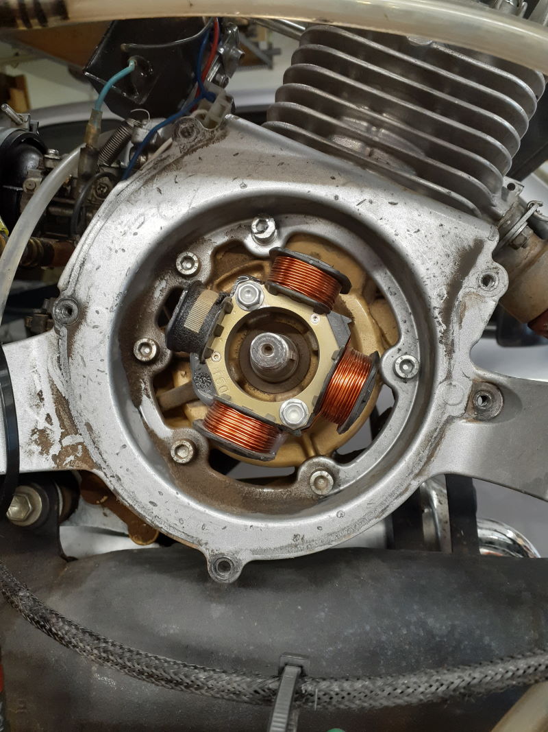
The ignition system consists of the exterior spark coil and the magneto which is located inside the front of the engine behind the flywheel. In the photo above the flywheel has been removed and shows the single black magnetor coil and three alternator coils for lighting and battery charging.
The flywheel has a permanent magnet in it which, when it passes by the magneto coil supplies a +70VDC pulse to the blue primary wire on the coil at just the right moment (a little before top dead center of the piston). The pulse is greatly amplified by the exterior spark coil and becomes a +20KV spark that ignites the fuel/air mixture inside the cylinder.
These coils are very durable and will last the entire life of the engine.
Failure
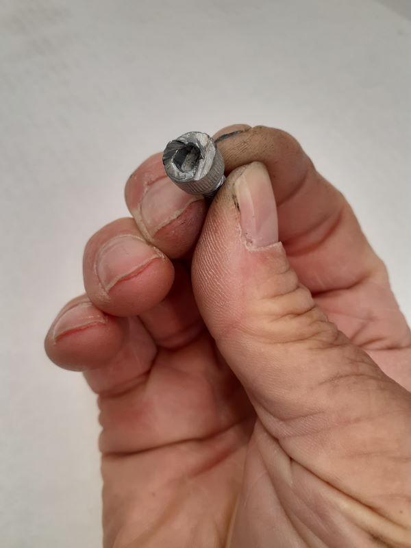
The rare times when they fail is usually due to wires vibrating loose or objects getting loose either inside or outside the flywheel. The flywheel has a strong magnet and it will nicely hold metal objects that can chew up one or more of the coils. It is very important when working near the flywheel that no small metal objects get near it!
One of the screws that hold the starter to the front of the engine came loose, got pulled in by the flywheel magnet, and started to chew up things. It was caught just in time!
Troubleshooting & other info
The coil can be easily tested with a spark tester. A good coil generates a 20KV spark at idle. A poor spark is usually due to a defective coil. Note: Some electric start engines may not spin the flywheel fast enough to generate a 20KV spark. In this case, a drill can be attached to the flywheel to spin it at 400-600 RPM.
The wiring from the magneto to the coil OR from the coil connections to ground OR the kill switch circuit are the primary cause of ignition problems. Periodically examine the wiring and be certain that each connection is solid and that there are no broken or loose wires/connectors. Also, be certain that the male and female connectors are fully pushed together.
This page has a schematic and resistance of a typical Thor magneto and ignition coil. This diagram has the dimensions and ratings of a typical Thor ignition coil. (diagrams courtesy of Dean Hannah)
Here is a typical wiring diagram (PDF) for the Thor engines including other Italian paramotors. The white wire (very hard to see and not labeled) in the lower photo of the wiring diagram is attached to the alternator under the flywheel and is the power source for charging a battery or running a headlight. The labels "C" and "B" identify the terminals and wire that connect the magneto to the kill switch ("C" terminal) and to the ignition coil ("B" terminal). Terminal and wire "A" connect to the engine block. Terminal "E" is for charging a battery (connects to thebattery "+" terminal). Terminal "D" connects the ground of the voltage regulator to the engine block.
Please refer to the wiring diagram (PDF) above regarding the following additional information:
1. The black secondary wire (not labeled) with the spark plug boot must be firmly connected to the spark plug. A break between the boot and the secondary wire is the most common point of failure. IDM ignition coil secondary resistance is 9K-12K Ohms (spark plug terminal to engine ground) depending on whether the secondary wire is resistance-type wire or not. Some engine coils can be 3.5-7K Ohms. The important point is that the resistance must not be infinite or less than 3.5k Ohms. Coils that are marginally bad will cause engine fade at high throttle settings but you will not be able to troubleshoot the coil unless you know the exact resistance value of a working coil.
2. The black wire labeled "A" must be grounded to the engine block. This wire is the ground wire for the coil and it will not work if this wire is loose. In fact, pilots may notice a shock through the metal parts of the throttle cable including the kill switch if they attempt to start the engine with this wire unconnected.
3. The blue wire labeled "B" is the primary wire of the coil and is connected to the magneto on the front of the engine and to the kill switch. It should have a resistance to ground of less than 4K Ohms when disconnected from the magneto. If you get an infinity value switch the Ohmmeter leads. It is rare that there is a problem with the coil itself. Breaks in the wires going to the coil are one of the most common ignition problems.
4. The wire labeled "C" (it can be any color) is the one connected to the kill switch. To measure the magneto resistance, disconnect connectors "B" and "C" and measure the value from either female connector to ground. Note: these connectors are connected together.) The magneto coil value should be 290 Ohms ± 10%. However, some Thor magnetos can have a resistance of up to 500 Ohms. Again, the important thing is that the resistance is not infinite or very low (1-10 Ohms). This PDF diagram has the resistance and a schematic of a Thor magneto and the coil. (diagram courtesy of Dean Hannah)
5. The "D" (ground), "E" (battery) and the white wire (alternator) connections are for the optional voltage regulator and are not used unless there is a battery.
Problems with wiring
Magneto systems are superior to ordinary systems because they have higher output and are more durable than ordinary ignition systems found on Italian paramotors. However, they are more sensitive to wiring faults because they have more wires. The connectors used by Miniplane, Polini, Vittorazi, and other manufacturers are fragile (not automotive grade) and may fail after as little as 100 hours of engine run time. If there is no spark, the first thing to check is the coil ground.
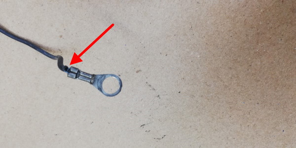
Below is a photo of a coil ground (black) wire which had a failed connection between the ring terminal and the wire itself. The insulation of the wire is still connected to the terminal but that is all. Engine vibration caused the copper wiring to fatigue and break right at the connector. It worked for quite a while until the space between the broken wires became sufficiently wide that the voltage could not jump the gap and the ignition failed. It was easy to repair with a quality terminal.
Note: terminals sold at Harbor Freight and auto parts stores are of inferior quality and should not be used. Quality terminals are expensive, often $0.35 ea. or more. The cheap terminals will not properly grip the wire and will slide off. Quality terminals require a special crimping tool. The only retail place I have found quality terminals is at Lowe's or Home Depot in the electrical section. 3M makes some of the best terminals.
Charging systems for electrical accessories
IDM magneto ignition systems include a 70 watt built-in alternator (the copper colored coils in the 1st photo on this page) for charging a 12V lead-acid battery. A regulator must be used to rectify and limit the alternator output voltage. The exact same ignition system is widely used in motorcycles, ATV's, go-karts, and lawn tractors.
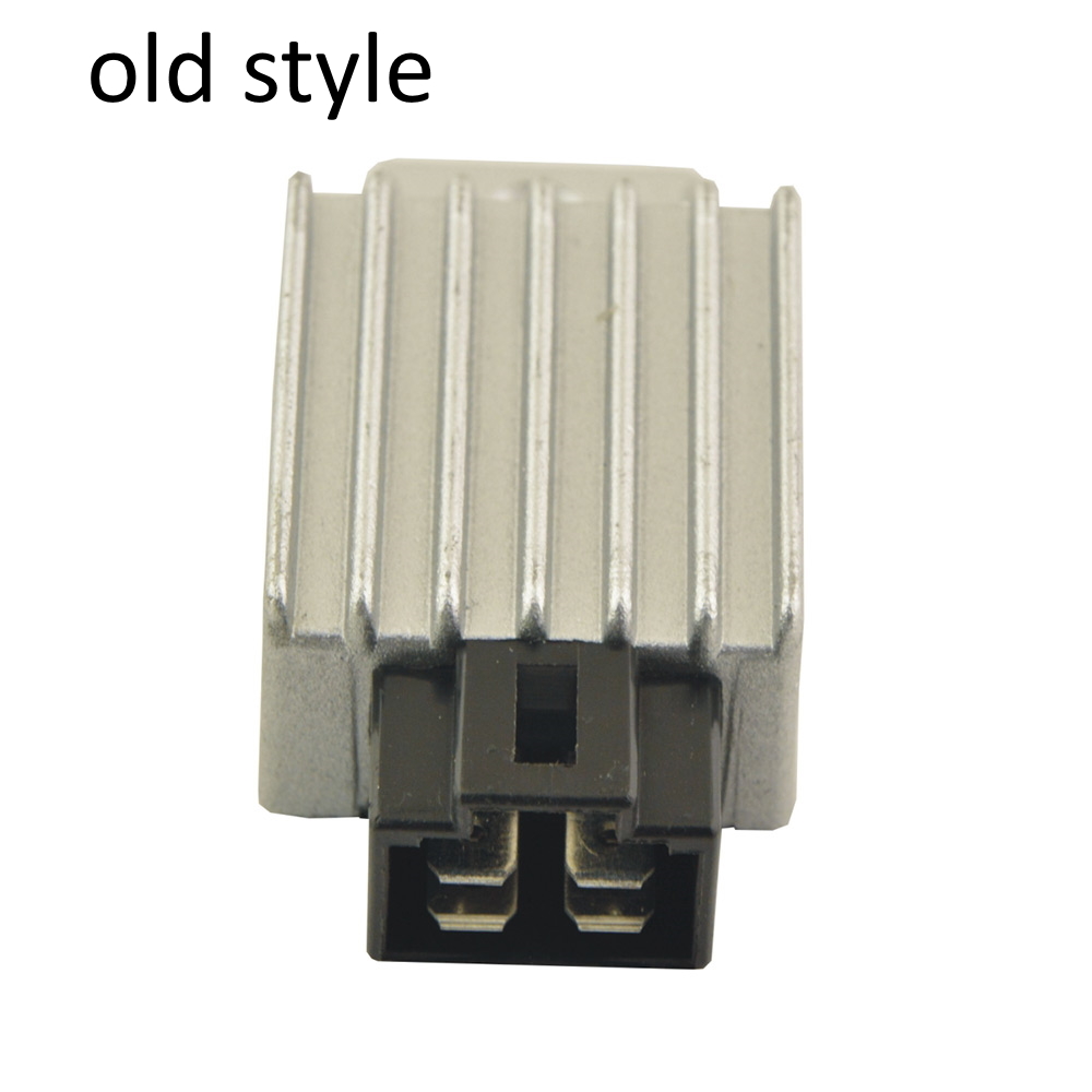
There are two types: the "old style" and the "new style". The wiring terminals on the Italian paramotors with magnetos fit one or the other style. These regulators are available on eBay for a fraction of the cost of the Italian OEM regulators and do the same thing.
This wiring diagram (PDF) has the regulator connection information for the four terminals of each regulator style (old or new). The "lamp" terminal is not normally used on paramotors. It can be used as a source for a filament head light. It is an AC voltage and cannot be used for strobe lights. The "battery" terminal has a 12VDC output and may be used for a strobe.
The so-called "old style" and "new style" can be on any Thor model.
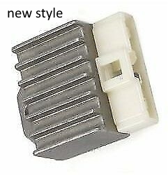
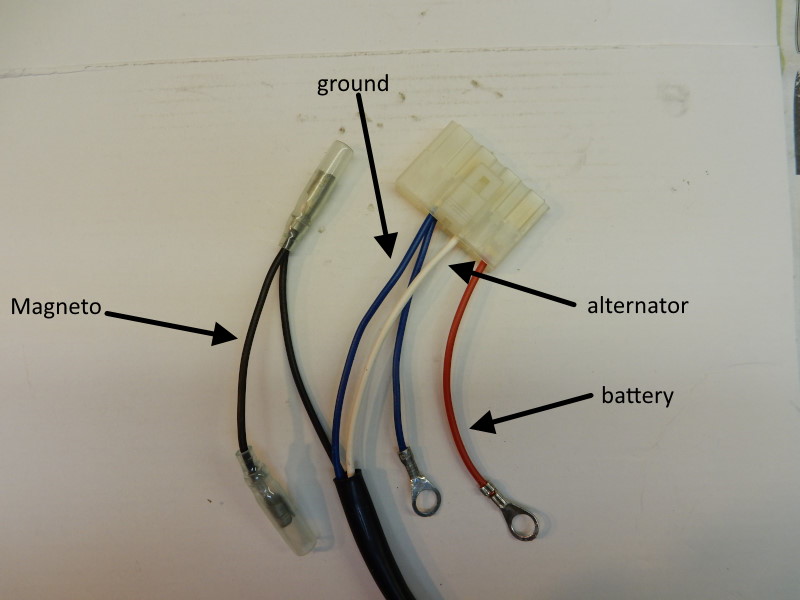
In the photo below of a "new style" regulator terminal, the black wire coming out of the cable assembly is from the magneto ignition coil and connects to the kill switch and as well as to blue wire from the coil.
The blue wire connects to ground. The white wire is the charging wire from the alternator and has a voltage at idle of around 21 volts AC. NEVER CONNECT THIS WIRE DIRECTLY TO A BATTERY! This wire must be connected to a regulator to prevent the battery from being overcharged and to rectify the voltage.
The red wire connects to the regulator via the connector and the other end (the ring terminal) connects to the plus side of a 12V battery.
If a battery and charging system are not being used, the red wire should be connected to ground so the wire does not flop around. Note: some engines, including the Minari, have different wire colors. Below is a typical "new style" connector. The empty terminal on the connector would be for a connector and wire to a headlamp.
![]()