

Fixing midrange roughness or two stroke four-cycling
by Had Robinson
Updated April 20, 2026
These instructions are for modifying Walbro WG and WB carburetors in order to correct an excessively rich mixture when engines are run in the midrange.
Note: pilots who install the Southwest Airsports FSM do-it-yourself project will not have to make the modifications given on this page
Note: if you are flying in temperatures less than 70F/21C, midrange roughness may be fixed by installing a preheat-system, an inexpensive and simple alternative to modifying the carburetor in various ways. Cold air is more dense than warm air and will result in a richer air/fuel mixture,
Discussion
Most paramotors run roughly ("4 cycle") in the midrange (4.5K-7.5K RPM) due to engine misfire from a rich fuel/air ratio. The problem is usually acute in the lower midrange. It gets worse at higher altitudes. At throttle settings near cruising speed, the engine may jump from misfiring to complete firing. The result is a surge and then a fade in RPM requiring the pilot to move the throttle back and forth. He may not be able to hold the engine speed at a particular RPM. As the engine "4-cycles", the vibration can also be annoying. In addition, fuel economy is effected. For example, a tuned Thor 130 will cruise (with a quality paraglider e.g. an Ozone with a lightweight pilot) straight and level at less than 0.5 gal/hr. With an un-tuned engine, this value can double. Thankfully, this problem does not harm the engine but it is a nuisance. The only advantage is that the engine will be less likely to overheat. As the engine is taken to full throttle the problem will disappear.
Why is this?
The paramotor manufacturers use stock Walbro carburetors which were designed for obsolete chainsaws and concrete saws e.g. Husqvarna 3120XP, 3120K, K960, K970. Unfortunately, there is not some easy method to lean out the midrange, like with the Bing carburetor. Nor were the Walbro carburetors designed for engines with the fuel tanks located 18"/45cm below the carburetor, a more serious problem that is a cause of engine overheating and stall at launch from wide open throttle, among other things.
The rich midrange issue is a result of increasing the main jet size/setting (done by the paramotor manufacturer) and the design of the idle/low speed circuit. The larger main jet size/setting is done to correct the inadequate output of the carburetor fuel pump due to the fuel tank being so far below the carburetor fuel inlet. As a result, the fuel/air ration during midrange operation is too rich.
This problem can be fixed by increasing the amount of air entering the engine through a throttle plate (TP) modification, by decreasing the amount of fuel entering the engine by plugging or restricting one of the idle progression holes (IPH), or by increasing the spring pressure on the metering lever valve. This page will only consider the TP and IPH mods as creating the shims requires greater technical skill.
Which modification is the best? In general, we only want to adjust the fuel/air mixture during midrange operation, not the high range.
However, it is a waste of time to do any modifications to the carburetor unless it is certain that the fuel supply system is in perfect order, the carburetor recently rebuilt, and a cylinder heat temperature gauge (CHT) is installed so the pilot can monitor the engine temperature during operation. If the fuel system and the carburetor are not in perfect order, the tendency is that engines will run lean rather than rich. An easy way to tell if an engine is running lean (stalling, sputtering, etc.) is to apply some choke (if there is one) with the throttle in the midrange. If the engine starts to run better, we know that we have a lean condition, not a rich condition. Performing this this modification if the engine is running lean will not fix midrange roughness due to a rich fuel/air mixture.
Definitions: IPH = idle progression holes TP = throttle plate Below are (4) ways to lean out the fuel/air mixture when flying at part or wide-open throttle. Of course, none of this would be necessary if most paramotors had the fuel tank at or near the level of the carburetor fuel inlet.
Adding a shim to the metering lever spring Increasing the spring pressure with a shim requires the metering lever diaphragm to exert a greater force on the valve in order to open it, leaning out the fuel/air mixture. The advantage of this mod over the others is that it is simple, easy, and does not make a permanent change to the carburetor. Some pilots have cut the spring or stretched it but doing this mod is difficult to replicate accurately compared to adding a shim. The downside of adding the shim is that the fuel/air mixture is changed over the entire throttle position range. We only need the midrange leaned out, not the mixture at wide open throttle and why I do not recommend doing this mod.
The IPH mod has proven to work with the WB carburetors but not the WG carburetors. In low/mid range operation in the WG, the idle progression holes (IPH) in the throat of the carburetor have a common well which not only contains fuel but also air. The air is introduced through an IPH that is on the atmospheric side of the throttle plate. At low TP settings, this air mixes with the fuel which not only helps prevent the formation of fuel puddles but also restricts the movement of fuel through the IPH. In tests, plugging an IPH in the WG tended to enrich the midrange even more. It also had unpredictable effects on the idle mixture adjustment. The WB does much better with the IPH mod.
The TP mod maintains the integrity and design of the IPH circuit. It works by virtually moving the idle progression holes away from the TP. The effect is that more air enters the engine with the same amount of fuel, leaning the fuel/air mixture at the lower midrange. The downside is that the mod affects the idle speed. If the TP is modified (cut) too far, the engine idle will be out of control. The FSM is the best option for WG but not the WB (do the IPH mod, instead).
In-the-air adjustments Some pilots have discovered that the closing the low speed jet a bit once they are flying helps smooth out the midrange. This is to be expected though it is not particularly convenient. The low speed system in diaphragm carburetors is active at all throttle settings (see the simple illustrations in the Zama manual).
To properly tune an engine for performance it is helpful to have some idea of how a diaphragm carburetor works. The Zama technical guide (a good Chinese knockoff of the Walbro) has basic information and illustrations of a typical diaphragm carburetor and is easier to understand and more relevant than the Walbro service manual (SM) which is over 30+ years out of date. There is no service manual for the WG series engines
Here are the parts diagram of the WG and the parts diagram of the WB.
- Do not make any changes to the carburetor unless you have installed a CHT. Before doing the modifications get a good idea of what the average running temperature of your engine is. It is easy to burn up engines.
- Rebuild and test the carburetor first if it has not been done recently. The diaphragm materials also function as check valves and pressure buffers on both the inlet and outlets of the carburetor fuel pump.
- Use only approved oils and ethanol-free gasoline, if possible. Ethanol fuels can lean out the fuel mixture.
If you do the modifications correctly, it will improve midrange operation. Thanks are due to the kart racing guys (the world experts on small engine carburetion), Gerry Farell, and Scott Travers for their input.
In-the-air adjustments can be done to the low speed jet to either the WG or WB carburetors if pilots would prefer not to make more permanent modificatios.
A. WB carburetor
The typical sub-model of the WB used for paramotors is the WB-37. It is simpler carburetor than the WG series. It has (2) idle progression holes (IPH) and no additional auxiliary jets. The WG has (4) IPH's and a special 3rd jet. The easiest way to lean out the midrange with the WB is by plugging an IPH with a piece of 0.5mm copper wire. This is because the WB has both an adjustable high and low speed jet. Also, the correct IPH is easily accessible, just below the idle circuit plate inside the carburetor.
Plugging an IPH
Materials needed: A few inches of 0.5mm (22 gauge) copper wire or equivalent. A smaller diameter wire may be used to only restrict fuel flow through an IPH. Old lamp or tool cords, hook-up wire, or any source of copper wire may be used.
1. Remove the air box. Disconnect the throttle return spring, if there is one. Disconnect the throttle cable, the fuel line, and the fuel pump hose going to the crankcase. Undo the nuts or bolts holding the carburetor to the engine.
2. Remove the carburetor and take it to a clean work area with plenty of lighting. Remove the metering diaphragm cover (#5), the diaphragm, and the circuit plate (#48) which exposes the idle progression holes. BEING CAREFUL USING METAL TOOLS WHILE WORKING INSIDE THE CARBURETOR. The soft metal used to manufacture carburetors is easily damaged, especially the tiny openings into the throat which are of a very precise diameter.
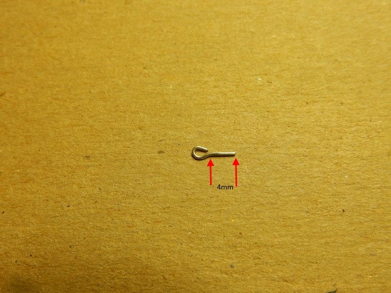
3. Cut a piece of the copper wire about 9mm long.
4. Make a loop with 5mm of wire at one end, as in the photo below. The portion of the wire opposite the loop will be about 4mm long. The loop in the end of the wire also aids in removing the wire with fine needle-nose pliers or tweezers if it is no longer needed.
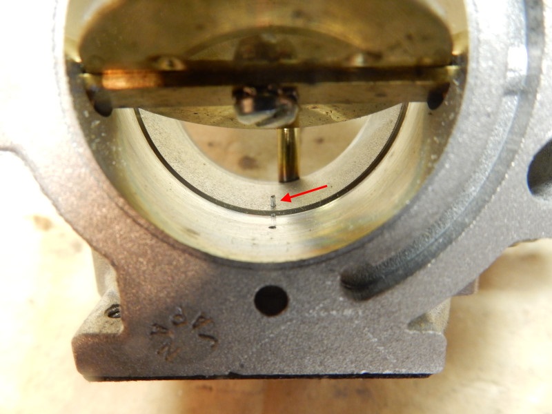
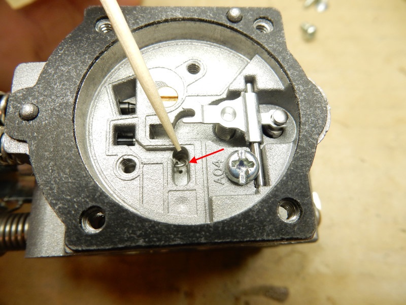
5. Put the wire through the idle progression hole closest to the center of the carburetor. This is the hole that affects the early parts of the midrange.
Use a felt-tipped pen to mark the portion of the wire that sticks into the carburetor throat. Remove the wire and cut it so that no part of the wire sticks into the throat. The TP must not contact the wire. The view here is from the engine side of the carburetor.
6. The loop makes it easy to remove the wire and it also keeps it from coming out once the circuit plate (or Welch plug in some carburetors) is installed. Even if the wire comes out, it will not do any harm except the midrange will be richer again.
7. Ensure that the throttle plate does not contact the wire that was put in the IPH.
8. Reassemble everything, start the engine, and adjust the low speed system (go to this link for the WB or this link for the WG). You will likely need to adjust the high speed system on the WB.
9. Test fly the engine while carefully observing the CHT. Most engines at sea level will be around 160-170ºC at full throttle and somewhat less when operating in the midrange. At our altitude (4,500' MSL), the range is 140-160ºC. Some engines, like the Minari, run much hotter than most. Be alert to a quick increase of temperature or the engine having "hiccups" in the midrange. These are signs that you are running too lean. After the modification, the midrange operating temperature will increase. During testing, if it ever starts climbing above 180ºC, STOP. It is easy to overheat engines, even during midrange operation. Different engines may react differently to this modification – and is another reason to be careful and patient when test flying the engine. Remember that it is always better to be a bit rich in the midrange than too lean.
If the mixture is too lean i.e. the motor is running too hot, the wire can be removed and a razor blade (X-acto knife) used to scrape away 0.1mm or more from the side of the wire, as needed. This will slightly richen the midrange air/fuel mixture. A smaller diameter wire can also be used. It is so easy to do this sort of testing on the WB.
B. WG carburetor throttle plate modification
The TP modification is best for the WG. A downside of the modifying the TP is that the idle can become too high if the notch is made too deep or the TP is installed incorrectly. Make sure you installed the TP correctly before assuming that the notch is too deep. However, if indeed the notch is too deep, a new TP will be needed.
The do-it-yourself project fuel system modification (FSM) eliminates the need for any carburetor modifications (other than changing out the main jet at higher altitudes). It should be ready sometime this spring. The FSM is more expensive than purchasing and modifying a throttle plate but it does a lot more.
It is a good idea to have some spare WG throttle plates (part #305) on hand if you are going to implement this modification.
By modifying the throttle plate (TP), the air fuel mixture can be leaned out in the midrange. Pilots should also reduce the size of the main jet if operating at high altitudes (4,000' MSL).
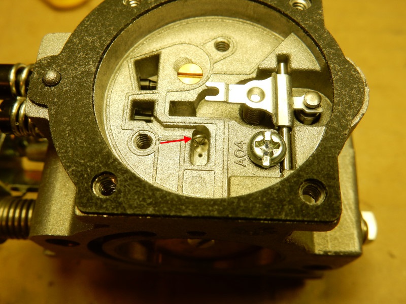
The photo below shows a WG carburetor from the engine side. The black arrow points to the modified notch (next to the "305" stamped on the TP) that moves over the idle progression holes. The green arrow points to the brass ball used to plug one of the bore holes of the idle/low speed circuit and can help pilots identify the correct notch to modify.
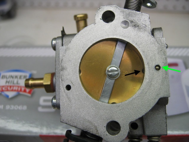
This fix increases the air going into the engine as the TP opens but not the amount of fuel. If effectively moves the IPH's closer to the center of the carburetor. The net result is that less fuel and more air enters the engine at the midrange throttle setting thus leaning out the mixture. Thanks are due to the kart racing guys for this way to modify a stock diaphragm carburetor.
Materials needed
- (1) WG throttle plate part #305
I installed the 112 jet, already had the throttle plate modified and took the first flight. It ran so much smoother at half throttle. Really big difference. CHT only got to 150 at full throttle. – K.R. Utah, Top 80 owner, high altitude
Modification steps
1. Remove the air box, if there is one. Disconnect the throttle return spring from the throttle lever that is on top of the carburetor. Disconnect the throttle wire and fuel line. Undo the two carburetor screws or nuts.
2. If there is a choke, disconnect it from the carburetor and get it out of the way.
3. Slide the carburetor off. You may be able to access the TP without having to disconnect the fuel line or the throttle cable. Use a felt tipped pen (Sharpie) to mark the correct notch (the notch with the red arrow in the photo above).
4. REMOVE the idle speed adjustment screw (the screw with the cone) It must be completely removed in order to reseat the plate later. Before beginning the next step, take a black felt-tipped pen and draw an arrow pointing to the correct notch. This will help by not mixing up the two notches on the TP.
5. Remove the screw that holds the TP to the throttle shaft and remove the TP.
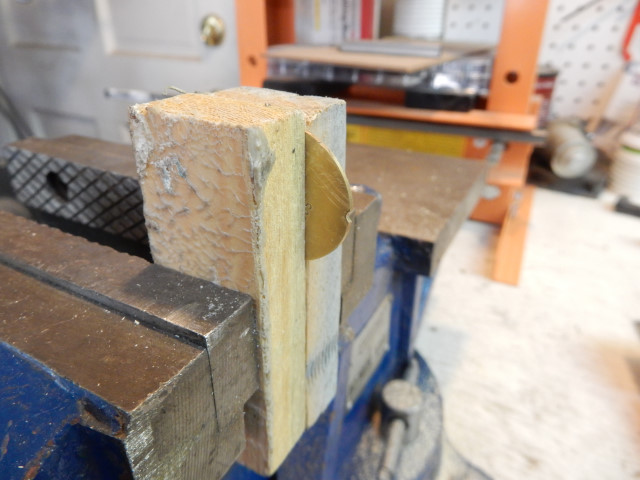
6. Place the TP in a vise. Be sure that the exposed notch is on the side of the TP that has "305" stamped on it and has the black arrow you made in step #3 above. This is the notch that passes the idle progression holes in the throat of the carburetor. Sandwich the plate between two pieces of wood. The TP can be on the side or the top, the latter makes it a bit easier to symmetrically enlarge the notch. Do NOT clamp directly on the TP with anything but soft wood or you may bend the plate and ruin it. It is a good idea to put some masking tape on the TP to further protect it from being bent when it is put in the vise. Only clamp the TP just enough to secure it. TAKE EXTREME CARE NOT TO BEND THE THROTTLE PLATE.
7. The existing notch is cut at a slight angle and is not perpendicular to the plane of the plate. The depth of the cut is the same distance from the perimeter of the plate. For best results, modify the notch at the same angle.
8. Using a round needle file (3.25mm), enlarge the notch. Go SLOW and compare the values below with what you are doing. Use a digital caliper to take the measurements. Use a safety razor blade over the top of the cut and measure from the blade to the bottom. The measurement is not from the tangent of the cut but it is good enough and provides a consistent reference point.
Because there are so many variables, use the starting cut value below and then test the engine. It is a bit of trouble but you will be able to lean out the midrange mixture to exactly the right amount by this method. If you make the cut too deep and wide the engine will have a runaway idle. If this happens, carefully measure and record the cut depth and width. Use another TP and decrease the cut dimensions by at least 10%.
Maintain the same cut angle (15º) as the original. Smooth any rough edges on the notch with a flat needle file or a wire brush on a Dremel-type tool. Use a scribe to note that the plate has been modified. It is important to measure the plate carefully and then note the dimensions somewhere. Every engine is a little different. For different carburetors, a good approximation would be to start with 50% increase in the stock notch dimensions.
Here are some starting values for engines that use the WG. At this time, we do not have sufficient data for the WB but adding 20% to the values here might be a place to start. Start with the lesser value and see what the slowest idle speed will be. If you overdo things, you will have to start over with a new throttle plate. As I have observed, doubling the dimensions results in a runaway idle speed (clutch engagement).
All altitude measurements in the table below are at MSL.
Stock value of the TP #305 notch adjacent to the idle progression holes/bore hole: 2.0mm x 0.70mmStarting cut value: 2.75mm x 1.13mm
Polini Thor 100, 130
Sea
level: 2.5mm x 1.0mm
3.5K' - 5.0K 3.25mm x 1.5mm Values greater than this
will give a runaway idle.
Top 80
Sea level: 3.5mm x 1.5mm
3.5K' - 5.0K': 3.8mm x 1.5mm
5.5K' - 8.0K': 4.0mm x 1.5mm
Values greater than this give a runaway idle.
Other engines
use the Polini Thor chart above
Pilots can be a great help to our flying community by sending the values that worked with your engine. Be sure to note the altitude at which you fly.
9. Replace the plate on the throttle shaft. The numbers on the plate must face out and the "305" must be adjacent to the plugged bore hole (green arrow in the photo above) and NOT the open hole on the carburetor (the hole opposite the plugged bore hole). Do not install the TP screw yet. The plate will ONLY center fully in carburetor throat if the idle speed adjustment screw is removed. In addition to the advice from Gerry Farell below, snap the throttle shut a number of times from just barely open to be certain that the throttle plate is centered in the throat of the carburetor BEFORE tightening the screw. The TP can be rotated very slightly with a toothpick so that the notch is centered over the 1st idle progression hole.
"When you place the throttle flap back, ensure it closes completely before tightening it to its shaft, and don't push too hard while tightening it or you will bend the delicate shaft. Add one small drop of [blue] threadlock to its central screw. Mount the carb on the engine and make sure the throttle cable permits the complete throttle assembly to open and return 'all the way' against the stop." – Gerry Farell
10. Screw in the idle speed adjustment screw until the TP just starts to open. This is an approximate setting.
11. Reassemble everything, start the engine, and adjust the low speed system (go to this link for instructions WG). The more the midrange performance improves, the more chance that you will not be able to adjust the idle low enough to keep the propeller from spinning in a clutched engine. If you cannot adjust the idle properly (too fast with the cone screw not contacting the throttle lever), get another throttle plate and start over with the notch dimensions 10% smaller.
12. Test fly the engine while observing the CHT. Most engines at sea level will be around 160-170ºC at full throttle and somewhat less when operating in the midrange. At our altitude (4,500' MSL), the range is 140-160ºC. Be alert to a quick increase of temperature or the engine having "hiccups". These are signs that you are running too lean. After the modification, the midrange operating temperature will increase. During testing, if it ever starts climbing above 180ºC, STOP. However, some engines, like the Minari, can tolerate much higher operating temperatures. The respective engine manual will have the maximum head temperatures that can be tolerated.
Different engines may react differently to these modifications – and it another reason to be careful and have extra throttle plates on hand in case you made a mistake.
![]()

