


Secondary 5mm wire replacement in paramotor engines
by Had Robinson
updated May 24, 2022
INSTRUCTIONS only for replacing the wire – NOTE: the coil does NOT have to be removed to replace the secondary wire.
To make a permanent repair (not replacement) of the secondary wire pilots can use this technique when: a.) the high voltage coil terminal is not easily accessible, b.) the secondary wire is not 5mm in diameter, or c.) it is a different coil than the IDM and does not have a typical HT terminal on the coil.
A. Discussion
This repair replaces the 5mm OEM secondary wire of the IDM ignition coil that is found in most Italian paramotors (e.g. Top 80, Minari, Vittorazi) with a premium quality wire that will last much longer, usually the life of the engine.
When this repair is completed, pilots will immediately notice an improvement in the high end performance of their engines if there had been sufficient time for the OEM wire to begin its decay process. If a temporary repair is needed, go to this page for instructions.
This repair is much easier to do than replacing the coil – on some engines it is a (3) hour job for an experienced mechanic vs. about an hour or less just to replace the secondary wire. If you replace the whole coil assembly, it can fail soon enough and you will have to do it again ... and again. It is rare that the coil itself is bad.
Pilots should also check the primary wire just to be sure it is OK. If it is open, the kill switch will not function.
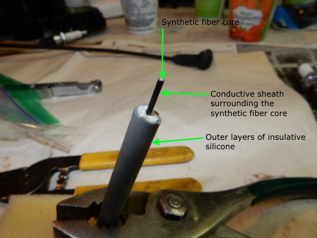
Small two cycle aviation engines all have a low flywheel mass to save weight. Consequently they all experience severe and damaging vibration. This leads to early failure of engine components, including the secondary ignition wire that goes from the coil to the spark plug. The OEM supplier (IDM) of the coil assembly uses a secondary wire that breaks and then burns out after a relatively short time. The core is made up of a carbon impregnated sheath surrounding hundreds of tiny flexible synthetic fibers that give it strength. In tests done here it is easy to break the Top 80 carbon sheath with modest flexing. Premium grade secondary wire does not use a carbon core but has a spirally wound wire core. This type of core will generally last the life of the engine.
The structure of a modern secondary ignition wire.
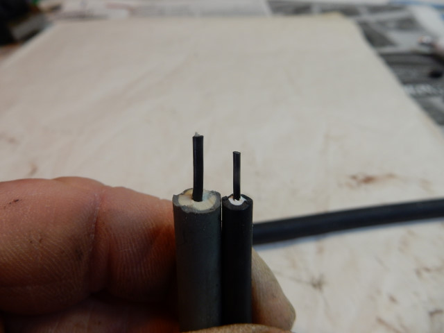
The automotive grade secondary wire above compared to the OEM Top 80 wire. Even the automotive grade carbon core wire will last much longer than the OEM wire.
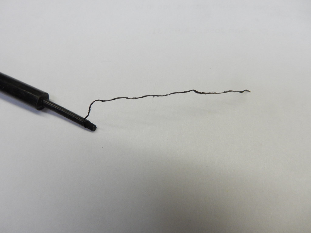
In the photo below, the spirally wound wire of the replacement secondary wire is exposed. Instead of a thin film of carbon surrounding the fibers of the inner core, it is wrapped with special wire that is much more durable than a carbon film. The core material of the Southwest Airsports replacement is made of Kevlar, an extremely durable fiber also used in armored vests. It will not break.
The resistance of this wire is 155 Ohms/ft. compared to a carbon core wire which has a resistance of about 6.8K Ohms/ft. The spiral wrapped wire also suppresses ignition interference with two-way radios.
B. Replacing the 5mm secondary wire with the Southwest Airsports kit
This repair should take less than an hour to complete.
Before you begin, check the coil to be sure it is good. If you need help on how to use a digital multimeter, Fluke has instructions here on how to measure resistance. Stick a sharp needle into the existing secondary wire about 7.5cm (3") from the coil. It must go in far enough to contact the carbon core in the center. Check the resistance from the needle to the engine ground (one of the aluminum cooling fins on the cylinder). It should be about 10K Ohms which is the resistance of a good coil plus the resistance of 7.5cm (3") of secondary wire on a Top 80 and other engines which have a resistor-type secondary wire.
Keep in mind that the measured resistance of the coil + the secondary wire can vary. I have not seen a good coil that has a resistance less than 8K Ohms. If the coil is less than this, it probably is bad and should be replaced.
Some engines will not have a resistor-type secondary wire and will have a lower resistance (and more ignition noise). If you do not see any resistance at first, withdraw the needle and stick it in again 12mm (1/2") closer to the coil. If no resistance is found, move the needle closer to the coil and check. Continue moving the needle closer to the coil, as needed. There must be a point at which resistance can be measured. If the secondary wire is bad right at the coil you will not be able to measure any resistance. If this is the case, remove the existing secondary wire entirely in order to measure the coil secondary resistance (see below for how to do this). If it is less than 10% of 10K Ohms (or open/infinite) in the IDM coil, the entire coil assembly must be replaced.
Special tools needed
- 1500 Watt dual temperature Heat Gun (572°F/1112°F or better) I would not use a propane torch unless you have a lot of experience with it.
- digital multimeter
- dielectric spark plug paste (not included in the kit but available in any auto parts or hardware store)
- Top 80 ONLY extra long 5mm hex bit. A complete kit of various metric hex bits is available on eBay. If you do not have this special hex bit, you will have to enlarge the access holes to the (4) screws which hold the cooling box to the face of the engine. Use an 8mm (5/16") bit to do this. The inexpensive bits from Harbor Freight can then fit in the enlarged holes. Note: you must correctly torque the cooling box screws when reinstalling them. An ordinary metric Allen wrench cannot do this!
Parts needed
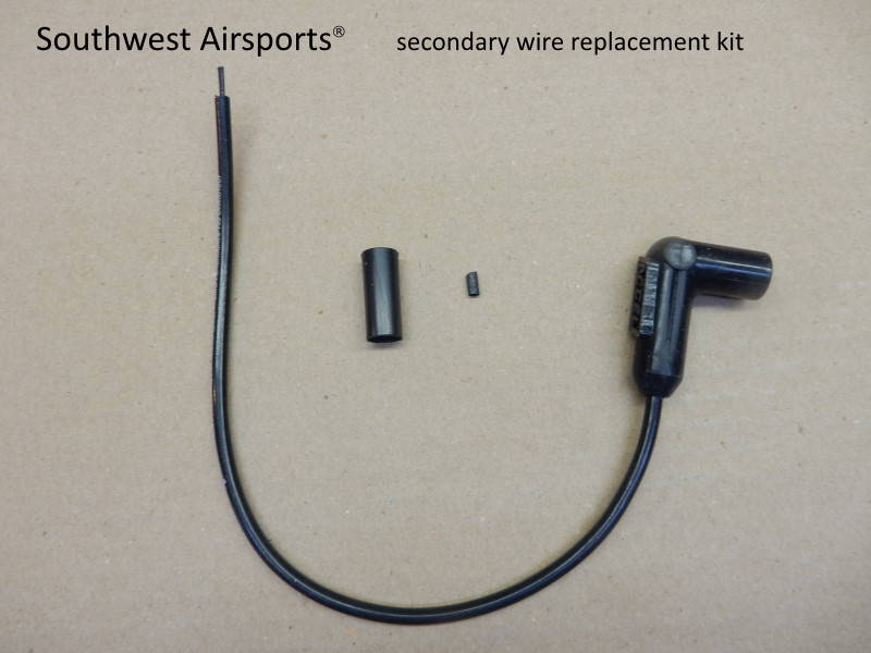
The Southwest Airsports Secondary Wire Replacement Kit is available from Miniplane-USA. The replacement secondary wire is 13" long and will fit most engines. Pilots may contact us for a kit with a custom length secondary wire. The kit includes:
- (1) 13" premium spiral core spark plug wire (red or black) with boot – always check the resistance of this replacement wire = approx. 160 Ohms.
- (1) small piece of heat shrink tubing
- (1) large piece of heat shrink tubing with a special inner adhesive
- URL for these installation instructions
Read through this section completely before beginning the actual repair. Study all of the photos so you know exactly what you are doing. Take a look at this video for some tips on the process. The video only shows the major steps. There have been some important changes that are given below that are not in the video. Remember that all Italian paramotors have IDM coils. Paramotors manufactured in other countries may ALSO have IDM coils, as well. The basic design of inexpensive motor cycle/scooter coils is the same, thankfully.
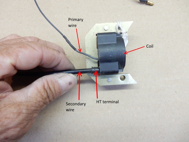
See this diagram for identification of the major parts of the coil.
1. Top 80 ONLY Remove the wire holding clamps on the engine and the cooling shroud from the old secondary wire – The clamp on the cooling air duct is held with a plastic screw. When replacing the clamp later, it is best to use a small metal screw for reattaching the clamp rather than the OEM plastic screw. You will need a drill and a 3.5mm (1/8") bit to remove the rivet that attaches the second clamp to the cooling box. Drill the head of the rivet just enough so that the head pops off. Remove the clamp and push the rest of the rivet through the cooling box with a nail. Find a small bolt and nut to reattach the clamp later. Be sure to use threadlock on the bolt and nut or it will loosen.
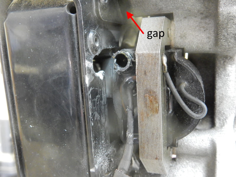
2. Top 80 ONLY Loosen the (4) screws which hold the cooling box to the engine using the extra long 5mm hex bit. Undo the screws about 5 turns. Pull the cooling box away from the coil terminal 5-6 mm (1/4") and leave it until you have completed the replacement. This will give you ample room to work on the coil. You can now easily use a Dremel-type tool or a round file to increase the clearance between the terminal and the cooling box as shown in the photo below.
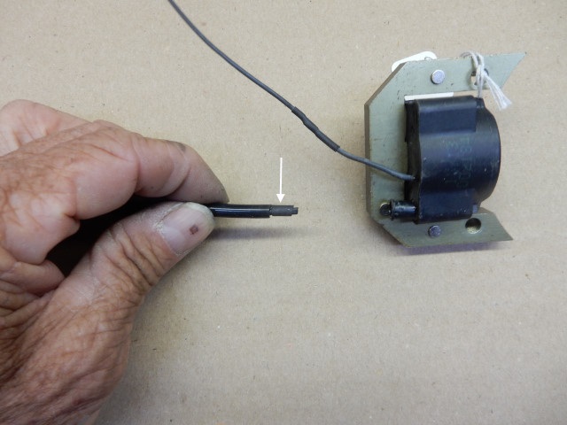
3. Remove the old wire from the coil – Note: on ALL engines, access to the high voltage terminal on the coil is mandatory.
You must have access to do this repair. Using a razor blade, slice the existing piece of heat shrink tubing (HST) lengthwise where it surrounds the old wire and high voltage
terminal at the coil.
(See this diagram for the parts of the coil.)
TAKE CARE TO JUST CUT THE HST AND NOT CUT THROUGH THE PLASTIC TERMINAL ON THE COIL. Peel off the old HST. Some coils may have a rubber
boot which can be sliced and removed the same way.
Using the hot air gun at the low setting, heat up the area where the wire enters the coil (see the
1st segment of the video). As you heat the area, gently pull on
the wire while making a circular motion with it. It
should take 45-60 seconds for things to get hot enough for the old glue to melt so that the old wire can be easily pulled out. It does not take much force to do this.
Do not get things too hot. If there is any smoke coming from the area, move the heat gun away from the area but continue to pull gently on the wire. If things get too hot, the high tension terminal housing and the internal connections could be damaged. That is, they will become blobs of melted goo and you will have to replace the entire coil assembly.
Use a cotton swab and copious amounts of rubbing alcohol to thoroughly clean the high tension (HT) terminal, inside and out. Use compressed air to dry the area and remove any small pieces of debris left inside the terminal. If you do not get it clean, little bits of aluminum or other particles left inside and on the HT metal post can short out the spark.
4. Check coil resistance Once the wire is removed, check the resistance of the coil AGAIN. Top 80: 8.5K Ohms ±10%, others similar. Some of the newer IDM coils in all paramotors may have a higher value which is never a problem. Coils with a low resistance e.g., less than 8K Ohms, should be replaced. Low resistance means that the coil has internal shorts and will not perform well. Alternately, the engine can be reassembled enough to test the coil by turning the crankshaft, as when starting the engine. A test lead (see "Essential toolkit") can be used to connect the HT terminal to a spark plug or (better) an ignition coil spark tester, crank the engine, and observe the spark. For more details on this test, see the quick ignition test.
DO NOT CONTINUE WITH THIS REPAIR UNLESS YOU ARE CERTAIN THAT THE COIL IS OK.
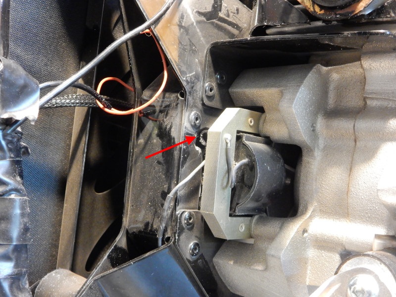
The photo above is the view directly looking down on engine. The red arrow points to the HV terminal on the coil. Inside is a barbed metal post that is connected to the secondary winding inside the coil. The photo below is a view of the coil from the left side of the engine. This is the typical location of the coil on most paramotors that do not have a Capacitive Discharge (CD) ignition system. CD systems have the coil mounted externally on the engine, usually near the head rather than adjacent to the flywheel.
5. Secure boot end of wire Temporarily secure the boot end of the new wire to the top of the engine near the spark plug hole with a piece of masking tape. This should be done so that there will not be any tugging on the end of the new wire while you are attaching it to the coil. If you attach the boot of the new wire to the spark plug you will just have to remove it again when you test the resistance of the new secondary wire before curing the HST. There is also a significant chance you will yank things if the boot is attached to the spark plug.
6. Install large HST piece Slide the large piece of HST onto the new wire.
7. Install small HST piece Slide the small piece of HST (white arrow) over the exposed core at the end of the new wire. (The photos below are with the coil off the engine for clarity.)
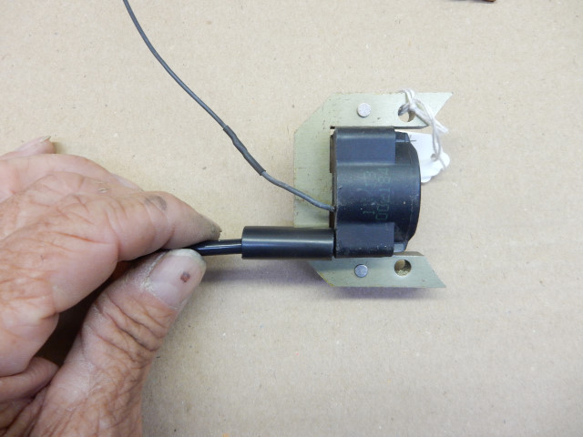
8. Install new wire in socket If this step is not done correctly, the repair will fail and you will have to start over with a new piece of HST. Gently push the wire into the high tension socket on the coil so that the barbed steel post slips inside the small piece of HST and solidly touches the core of the new secondary wire. You will know you have done it correctly if you can very gently pull on the wire and it does not pull out. The wire must be completely inserted into the socket and none of the core should be showing.
9. Test the resistance of the new wire – You MUST check the resistance of the new wire assembly before you make the connection permanent to be certain that the new wire and the coil are electrically connected together. With the multimeter, measure the resistance of the wire from the spark plug terminal inside the boot to a cooling fin on the engine. The resistance should be 8.8K Ohms ±10%. New models of the Top 80 and other engines may have a different value but it must *NOT* be infinite or less than 8K Ohms.
10. Slide the big piece of HST over the high tension terminal on the coil.
11. Apply low heat with the gun, moving the gun back and forth over the HST. Be careful not to burn up the HST tubing – take your time to do this correctly. If you have a thermometer, the best temperature of the air coming out of the heat gun should be 110ºC (256ºF). The minimum curing temperature of the gun must be 60ºC (140ºF).
As you apply heat, you will see the HST start to shrink around the terminal and the wire. The HST tends to slide off the terminal as it is heated due to the slippery nature of the hot adhesive inside. Use a short stick, a pencil, etc. to hold the HST in place while it is cooling. If you use your finger you will discover why you should have used a short stick, a pencil, etc.
Keep applying heat until you see the adhesive ooze out of the ends of the HST. When this happens, STOP APPLYING HEAT IMMEDIATELY.
Continue to hold the HST in place for at least one minute after heat is removed.
Do NOT move ANYTHING until everything cools down completely. It can take a full minute or more. Do not be impatient!
The special adhesive in the HST will firmly grab the new wire and hold it on to the high tension terminal as well as seal the connection from water, oil, and dirt. Ordinary HST will not grasp the new wire securely and engine vibration will quickly cause the new secondary wire to come loose.
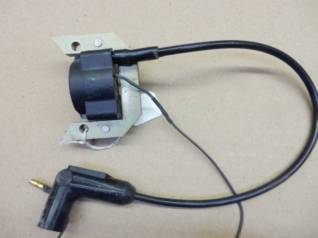
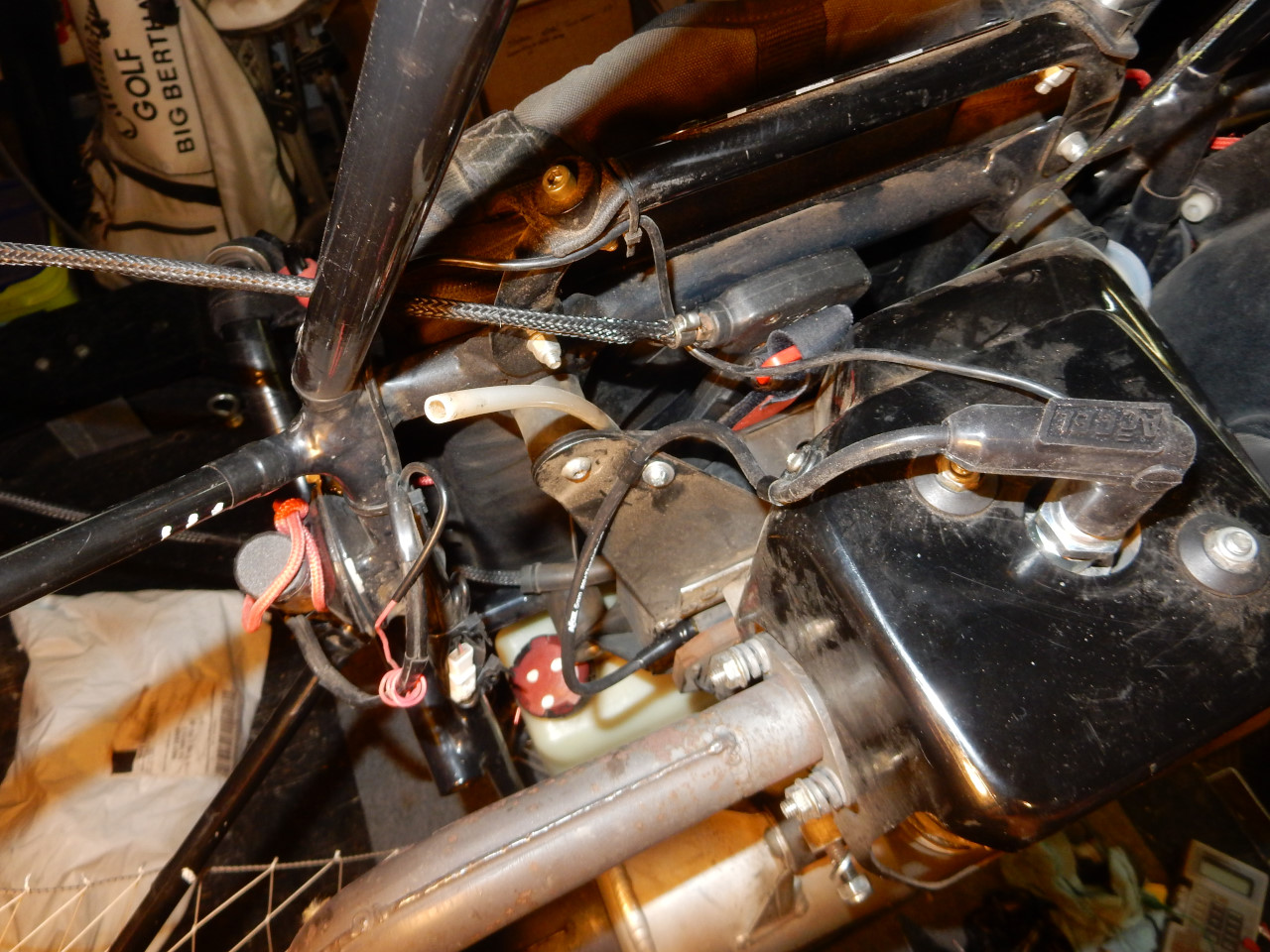
Below is a photo of the how the completed connection should look like. When you have done this, you will have a coil assembly that will last the life of the engine.
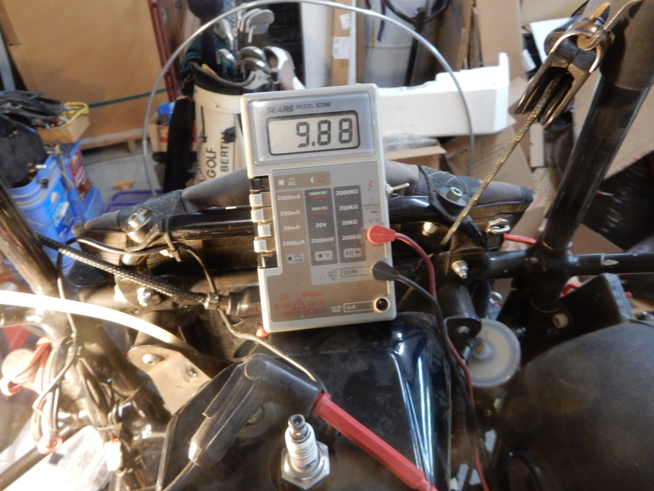
12. Check the resistance again of the new wire to ground. Note: some ignition systems may have a higher resistance than the value (9.88k Ohms) shown here.
13. Top 80 ONLY Reattach the secondary wire to the engine cowling and the cooling box using the existing clamps. THIS MUST BE DONE or the new wire may be destroyed by the intense vibrations of the engine.
14. Attach the boot to the spark plug. It is a good idea to apply a small amount of Spark Guard (dielectric paste) to the inside of the boot and to the terminal on the spark plug. A toothpick works well to spread the paste around. The boot should be gently twisted and pushed down over the plug. The boot is correctly seated when the gap between the bottom of the boot and metal base of the plug is about 1/8" (4mm). If the boot is not correctly attached, the engine vibration will destroy the internals of the new spark plug boot.
Do not forget to apply red threadlock to the spark plug terminal if it is a screw-on type.
15. Top 80 ONLY Retighten the (4) screws which hold the cooling box to the engine to 10 Nm.
Note: for other engines, reassemble as required.
It is a good idea to test fly the engine after making repairs like this one.
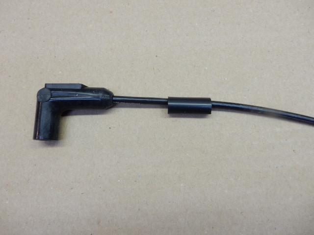
The completed installation. This fix for the secondary wire uses the same method of fastening the wire as the factory but the components are of superior quality.
![]()