


Ignition coil – service, replacement, & adjustment
by Had Robinson
updated June 16, 2022
Discussion
Note: The Minari models and the Moster 185 have the same ignition coil as the Top 80. Newer models of these engines, however, may have more advanced (and better) IDM ignition systems. Procedures for servicing and testing the coil are identical for all engines except setting the timing. Polini uses a higher quality ignition system than most others and requires less maintenance. This is because Polini, some Vittorazi engines, and others have the ignition timing fixed. These engines do not require the timing to be set manually – a huge time saver when replacing the coil.
Precisely setting the timing and having a high spark voltage will ensure that any engine will have maximum power output. Adjustments to the timing can also dramatically affect the life of the engine. Do not attempt to time the engine unless you have good mechanical skills. With a few modest tools, pilots can check the timing of their engines. Thankfully, this is not needed unless the flywheel has been removed.
It is rare that the coil fails (no spark or a weak spark). Most of the time it is the secondary wire (the long thick wire that goes from the coil to the spark plug) that fails. The secondary wire can be replaced, if necessary. Many engines have a secondary wire with an inner carbon core which eventually breaks from the severe vibrations of the engine. Over time (25-50 hours) the core burns back, forming a gap inside the wire which widens over time until the spark cannot cross the gap. As the pressures inside the cylinder increase from opening the throttle more and more, the voltage required to cross the gap of the spark plug also increases. If the coil cannot produce the required voltage, engine output will fade or the engine will stumble or stop. At the same time, the internal voltages inside the coil will increase and stress the coil insulation which can eventually short to ground – but it is a slow process.
Note: ignition failure does not cause engine overheating. On the other hand, fuel starvation will. This is how pilots can tell the difference between ignition failure and fuel starvation.
A. Checking coil output, secondary wire integrity, and spark plug boot condition
Before replacing any parts, test the ignition system in order to find out which part(s) has failed.
B. Checking the coil to flywheel gap
IDM, the manufacturer of the coils and flywheels for Italian paramotors, specifies a gap of 0.35mm - 0.45mm. The Top 80 website specifies a gap of 0.30mm (0.012") but new engines from the factory have the gap set to 0.38 mm (0.015"). The bottom line is that the gap could be from 0.30mm - 0.45mm. Too great a coil gap will cause hard starting and slightly retards the spark. If the gap needs to be changed, see "Replacing the coil or changing the coil gap" at the end of this article. The gap is not a critical value, thankfully.
However, if the flywheel and coil ever come in contact with each other while the engine is running, the coil will be damaged and coil output will suffer. If this has happened, the coil must be replaced.
All engines Do not waste time checking the coil if the fuel system has not been checked FIRST. Note: missing or roughness in the midrange is caused by the nearly universal problem of locating the fuel tank far below the carburetor inlet. Engine manufacturers must increase the main jet size in order to prevent fuel starvation at full throttle but this also affects the midrange, as well. Installing the FSM is the only permanent and effective solution to midrange hiccups.
Checking the coil gap can be done without disassembling most engines. However, a feeler gauge with a narrow blade must be used. Ordinary feeler gauges will not fit in the tight space between the coil and the engine.
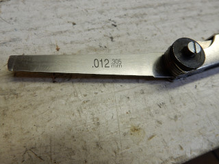
Checking the coil gap on the Top 80 without disassembling the engine (below). It is a good idea, however, to remove the muffler when doing this.
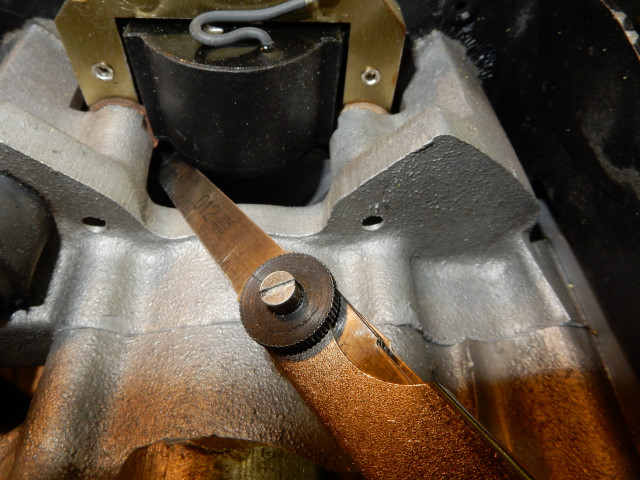
As the gap increases, the voltage output of the coil decreases (but only at low RPM) and the spark timing advances (fires later). Pilots will want the gap to be exactly as specified for maximum spark output when starting the engine and for the correct timing.
C. Coil service (for the Top 80, others are similar)
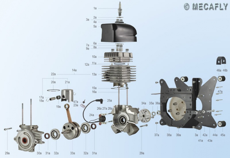
If you are not sure about the names and location of the parts of the Top 80 or paramotors in general, see these diagrams. For other engines, consult the owner's manual for part identification and location. All Italian paramotors that we have seen in our shop use IDM ignition systems which is why this section is helpful regardless of the engine manufacturer.
Special tools needed:
- Top 80 only: 3/8" drive metric extra long hex bit socket set (if you only have the
standard length bits, you can easily widen the holes in the cooling box with a drill)
Parts:
- Ignition coil
- Top 80 only: Finger screws (new or modified)
- Top 80 only: 5/32" medium rivet
Top 80 only: Do not attempt this procedure unless you have a set of new finger screws or have modified them. DO NOT REUSE FINGER SCREWS UNLESS THEY HAVE BEEN MODIFIED.
This is the most difficult and time consuming routine service procedure with the Top 80 engine and will take about (3) hours for an experienced mechanic to do. Other engines are much easier to service.
Miniplane has been supplying some IDM coils that have one or both mounting holes machined .003" ± off so that the coil gap cannot be set correctly. This can be easily fixed by enlarging the holes slightly with a Dremel type tool with a grinding stone towards the outside of the coil. Do not enlarge the holes with a drill bit because it will likely short out the coil sheaves and may ruin the coil. These IDM coils are scooter/lawnmower grade and are neither durable nor particularly well made and must be treated with care. Hopefully, Miniplane might someday specify a better coil that will last the life of the engine. Meanwhile, we have to deal with this headache.
It is not a bad idea to take photographs of the engine as you take it apart. There may be fittings and parts that go back a certain way and you may forget where they go.
The steps below are for the Miniplane Top 80, others similar.
1. Remove the exhaust system and then the engine from the frame. The exhaust system will be in the way if it is not removed. The exhaust system has (2) button-head screws that hold the muffler to the lower part of the engine and (2) nuts with springs that hold the exhaust pipe to the cylinder head. Do NOT remove the (2) studs that go into the cylinder head. These studs should be checked to be sure they are not loose. They must always be installed with blue or red threadlock.
2. Remove the cooling air duct The top of the duct has (2) nuts and plastic washers which must be removed. Remove the plastic screw which attaches the secondary wire to the duct. Clip the "ears" of the duct where it surrounds the exhaust pipe. Even if the exhaust system is not removed, the exhaust port has (2) studs which stick out enough to be caught by the "ears" on the duct. These ears do not have any use and are in the way. Cut them off.
Reinstallation: Be sure the duct is correctly placed. It should slide on easily and not jam. The plastic screw used to fasten the secondary wire strap to the duct is flimsy. It is better to use a #8 sheet metal screw or similar. Orient the strap so that it is between the hole and the center of the engine.
3. Remove the starter The (3) small screws have lock washers. Be careful not to lose them.
Reinstallation: When reassembling the starter to the cooling box, this photo gives some help o how to hold the pawls in the right position.
4. Remove the finger screws Unless modified finger screws were used, it will be necessary to grind down the ends of the finger screws so that the washers, pawls, and springs can be removed and a 10mm deep socket used to remove the screws. Only grind away just enough of the screw so that the washer pops off using a pair of pliers. DO NOT GRIND THE WASHERS – YOU MAY NEED THEM SOMEDAY. Remove the pawls and springs. Remove the finger screws with 10mm deep socket along with the pawl holder and spacers.
Reinstallation: reference this page for more information on how to reinstall the finger screws correctly. Torque the screws to 10 Nm. Use a long piece of 3/16" flat steel plate x 1" to slip between the cooling fan and the cooling box to hold the flywheel from turning while torqueing the finger screws. Alternately, remove the redrive and hold the clutch with an oil filter wrench or a nylon strap. (See the clutch page on how to use a strap to hold the clutch from rotating.)
Some have managed to loosen and remove the finger screws by getting a thin end-wrench on them. However, it is impossible to torque the screws to the correct value during reinstallation without having the pawls and springs removed. Some claim to be able to reinstall the finger screws with the pawls and springs attached – but they invariably bend the springs and/or the spring stops and/or wreck the screws. Don't be a tool-monkey. If the cooling fan is not torqued down properly it can move enough to cause vibration at high engine speeds and carve holes where it attaches to the flywheel.
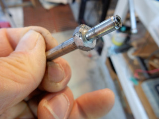
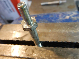
Damaged Top 80 finger screw due to installation without grinding the tips off and using an ordinary end wrench instead of a 10mm deep socket. Other parts of the starter mechanism were damaged, as well.
5. Remove the primary wire Use a 5/32" bit to drill out the rivet head that holds the primary wire to the bottom of the cooling box. Do it just enough so that the head of the rivet is removed. Do NOT continue to drill the actual rivet that is in the cooling box. Once the head of the rivet is removed, the clip and wire will pop off. Use a 1/8" punch (or equivalent) to punch out the rivet that is in the cowling.
Reinstallation: When reinstalling the rivet, orient the clamp so that it faces the rear of the engine.
6. Remove the cooling box (cowling) along with the cooling fan. You will need an extra long 5mm hex bit to do this. Note: the cooling fan cannot be replaced without removing the rivets that hold the cooling box together so be careful with the cooling fan.
Reinstallation: Use BLUE threadlock on the (4) screws which hold the cooling box on the engine. Use a magnet tool to position the screws over the holes in the cooling box. It will save a lot time. Torque to 10 Nm. Use the new/modified finger screws to temporarily hold the cooling fan in place as it tends to get in the way and may be damaged when attaching the cooling box to the engine.
7. Remove the coil Remove the (2) screws which attach the coil to the engine. Be sure to save the (2) fiber washers that are between the coil and the holes on the
engine. Note the orientation of the fiber washers (Top 80) and put them back exactly the same way.
8. Mount fiber washers Put the fiber washers (if used) on the coil mounting surfaces on the crankcase. If the old washers are used, align them carefully so that the machined surfaces on the crankcase and imprints on the
washers line up. Use a small dab of rubber cement or RTV sealant to hold them in place. If the washers are misaligned it may change the alignment of the coil with the flywheel and the
gap will not be uniform.
9. Attach the (new) coil with the secondary wire towards the TOP of the engine. Hand tighten the screws. Threadlock is not needed on these screws. The coil must be installed with the secondary wire towards the top of the engine or it will not work correctly due to polarity of the electronics inside the coil. Note: the Mecafly illustration shows the coil installed incorrectly (it may be an accidental mirror image).
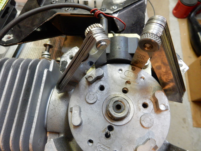
10. Adjust the gap Two feeler gauges must be used. This is because the coil will rotate on one screw when the gap is adjusted on the opposite side. The slight rotation of the coil when it is moved to adjust the gap on one side will affect the other side.
Place a gauge between each end of the coil and the flywheel at exact location shown in the photo below. Set the gap to 0.38mm (0.015"). Thankfully, the gap is not critical to coil output at high rpm. The less the gap, the easier the engine will start. Be absolutely certain that the coil does not contact the flywheel.
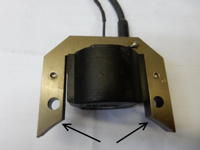
The coil has two points where the gap must be checked between them and the flywheel (see photo below). The gap specified is the minimum between any part of the coil and the flywheel. Note the orientation of the coil – the secondary wire is up. If it is installed upside down, the coil will not work.
Push the coil firmly against the gauges and snug up the mounting screws to (1) Nm or less. Check the gaps again to be sure they are correct. If all is OK, tighten the screws to the correct torque (4-5 Nm) and check the gap again. It will be usually somewhat less. As long as it is not less than 0.30mm, it will be OK.
If the gap is too great, the engine may not start as easily. If the gap is too small (< 0.30mm), there is the risk that the coil and flywheel might touch as the flywheel heats up and expands when the engine is run. If they touch, the coil will be ruined from a shorting of the iron sheaves.
The Miniplane service site ("accensione ignition" section) has some photos of the coil and where the gap should be measured if the above photo is unclear.
After the coil is gapped correctly, the ignition timing may be checked (if the flywheel was removed) and re-timed, if needed. Ordinarily, this is rarely needed.
11. Reassemble the engine It is the reverse of the above steps starting at step #6.
![]()

