


Setting the ignition timing on paramotors
by Had Robinson
updated August 3, 2023
If only the timing needs to be checked, go to this page. Note: most paramotors now have the ignition timing fixed. Before wasting your time on this page, determine if your engine will allow the timing to be adjusted. At this time, only the Top 80 and the Minari allow the ignition timing to be adjusted. There may be engines unknown to us which allow the timing to be adjusted. If pilots have such an engine, it probably is best to follow the instructions for the Top 80.
Why have adjustable timing? Those who fly at high altitude (>5K' MSL) might want to advance their timing a few degrees to increase performance. Those who cannot get decent gasoline may want to retard the timing a few degrees in order to suppress engine knock, which is very destructive of the mechanical parts. Others may want to retard the timing a few degrees to make engine starting much easier and less punishing on electric and manual starters. The cost of retarding the timing a few degrees is less horsepower at the various throttle settings. Remember: maximum engine performance is a trade-off for increased maintenance and more frequent overhauls. If you fly a big engine, do you really need to have the rated power? However, retarding the timing on small engines, like the Top 80, would be noticeable and probably not a good idea. If you rarely fly at full throttle, especially at launch, consider retarding the timing 2-4 degrees. See how the engine responds for your needs. Make sure you have a CHT installed as the temperature will usually rise a bit.
If the timing is too far advanced, the engine will knock, which can destroy it. If the timing is too far retarded, the engine will lack power and may overheat if the timing is retarded too far. Every engine is different.
The instructions below are for the Top 80 and older Minari models which are among the paramotors that do have adjustable ignition timing. These motors do not have a movable coil assembly. For this reason, the flywheel has to be clocked relative to the crankshaft. It is much harder to time these types of engines.
If you have a movable coil on your motor, you are fortunate and the job of setting the timing is much easier.
IT IS ALWAYS SAFER TO BE ONE OR TWO DEGREES ON THE LOW SIDE (RETARDED) THAN ON THE HIGH SIDE (ADVANCED).
Clutched and non-clutched engines often have different values due to the lack of inertia in clutched engines that is required to "kick" the piston past TDC (top dead center). Those who have clutched engines with a non-flash starter know how difficult they can be to start.
Before beginning, be sure that you have the correct timing values for your engine.
A. Special tools and parts required
1. Top dead center (TDC) indicator 10mm or 14mm
Note: the problem with all TDC indicators is: will it clear the cooling fins? The indicators listed below work with all paramotors.
14mm PVL TDC indicator $79 free shipping
10mm SWA TDC indicator $75 free shipping
If you already have a dial gauge indicator and a 14mm spark plug hole, Laser Tools makes a TDC adapter available on eBay.
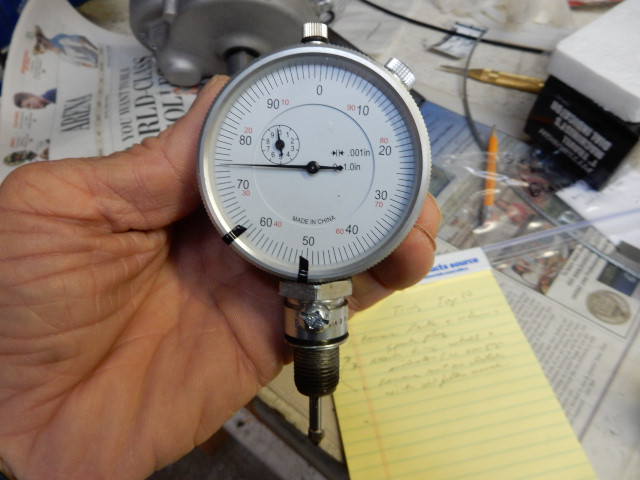
Alternately, a TDC indicator tool can be made from an old spark plug (10mm or 14mm) and an inexpensive dial indicator (about $15 from Harbor Freight).
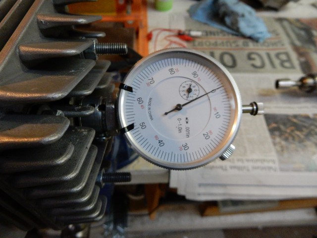
Here are the details of the dial indicator and the homemade holder for attaching it to the cylinder head. Be sure to shorten the threads on the used spark plug to a 1/2" or so (not yet done on the plug case below). Cutting excess threads off will decrease the number of turns you have to screw the tool into the cylinder head. Use a file or grinder to remove the chamfered edge at the top of the metal part of the plug. Once this is gone, the inner assembly of the plug can be easily removed. The dial gauge can then be set inside the hollow plug body with a set screw (best) or with some quick epoxy. The 10mm version may require some additional drilling of the spark plug body.
2. Top 80 only: Long-reach metric hex bit set – Tekton makes a set for around $22 U.S. If the cheaper Harbor Freight item (#67890) is used, the access holes in the cooling box will have to be drilled out to 8mm (5/16") in order to fit the shank of the tool.
3. Top 80 only: Replacement finger screws. Pilots who have modest mechanical skills can also modify them for reuse. This is recommended for pilots who do their own engine work. It is impossible to correctly torque the finger screws when reinstalling them unless the pawls and springs are removed. The cooling fan spins at over 9,000 RPM and must be properly attached.
4. Flywheel puller – It is necessary to use a wheel puller in order to safely loosen (or remove) the flywheel from the crankshaft. Miniplane-USA has the exact puller for the flywheels of various engines. However, all of the tools made by the paramotor manufacturers are not of hardened steel but are similar to homemade tools. BE CAREFUL WITH THEM AS THEY ARE EASY TO BREAK/BEND. The Harbor Freight wheel puller may not it so, if in doubt, use the specific puller made for your engine. You may have to invest in a professional grade puller to remove a stubborn flywheel. See the paramotor rebuilding page for more info on how to remove the flywheel.
Some engines have a movable coil (NOT the Top 80) and do not require the flywheel to be loosened and rotated in order to time the engine. These engines have a key on the crankshaft to ensure the flywheel is always in the same position (e.g. the Thor engines). If your engine has a key in the crankshaft that fits a slot in flywheel and also has a movable coil, the engine can have the timing adjusted. However, most engines with a keyed flywheel do not have a movable coil. The timing is fixed and cannot be changed on these types of engines.
Alternately, engines like the Top 80 do not have a key in the flywheel and it must be rotated in relation to the crankshaft in order to time it.
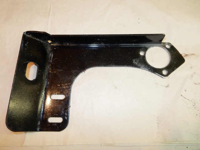
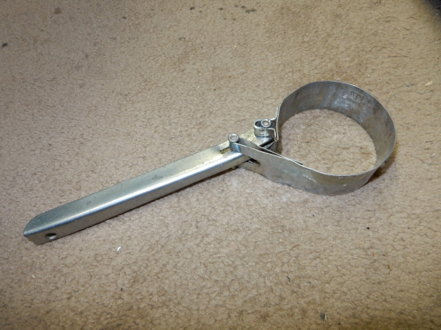
5. Some method to hold the flywheel (or the other end of the crankshaft) so that the flywheel nut can be removed. A socket on the opposite crankshaft nut can be used to tighten the flywheel nut but to loosen it. A small oil filter wrench can be used to hold the clutch (Top 80), a tie down strap, a Vise-Grip chain wrench on the clutch (Top 80) or flywheel, or a homemade tool to hold the flywheel such as this one for the Top 80. Do not use chain wrenches that have teeth. will ruin the clutch.
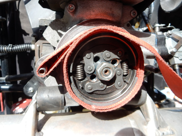
Use a tie-down strap and wrap it around the Top 80 clutch four or five times. Double it back around one of the redrive studs and stuff it under itself.
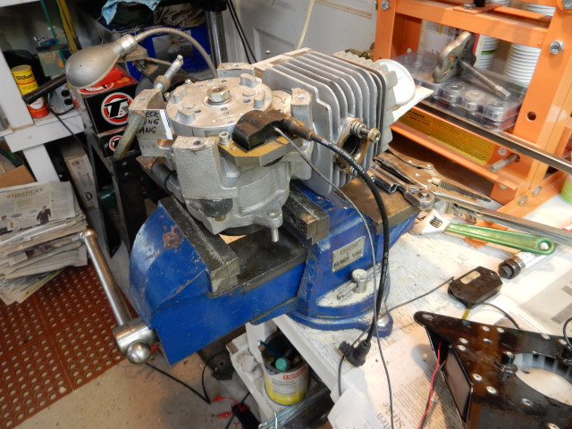
6. Bench vise and, as needed, a custom drilled steel or plywood plate to firmly hold the engine while working on it. Clamping one of the motor mounts in a vise is not a safe way to secure the engine. The board could be mounted to a table with clamps. Whatever way is used, the motor must not be able to move while you are working on it.
B. Steps to set the ignition timing
The Top 80 and the Minari, for example, have identical ignition systems. However, they have different steps in setting the timing. The Minari technique is easier to do than the Top 80. Always check the timing after you have completed the steps below to be sure it is set correctly.
1. Remove the engine from the frame and attach it to some immovable working surface.
2. Remove the pull starter assembly.
Top 80: The starter pawls and finger screws must be removed so that you can remove the cooling fan and the cooling box. (See the removal section of "finger screw and starter pawl removal and assembly" on how to remove these parts.) The cooling box and cooling fan are removed as a unit. Unless you the modified finger screws, the cooling fan cannot be removed with out drilling out all of the rivets on the cooling box and separating the cover and the box. For reinstallation, see this page for help with how to hold the pawls in the correct position when reattaching the starter to the cooling box.
Top 80: Cooling box and fan removal Using a long reach 5mm hex bit, remove the (4) socket head screws that attach the cooling box to the engine. If you do not have the long reach bits, you will have to drill out the holes that are used to access the screws by a few mm's. Note: the cooling fan comes off with the cooling box. It cannot be removed from inside the cooling box without disassembling the cooling box by removing all of the rivets which hold it together.
Reassembly is the reverse. Torque the 6mm cap head screws that hold the cooling box to the engine to 10 Nm. Use a 4mm (5/32") bit to drill out the rivet head that holds the primary wire to the cooling box. Do it just enough so that the head of the rivet is removed. Do NOT continue to drill the actual rivet that is in the cooling box. Once the head of the rivet is removed, the clip and wire will pop off. Use a 3mm (1/8") punch to punch out the rest of the rivet. Removing the cooling box exposes the flywheel and the ignition coil. Rivet reinstallation: When reinstalling the rivet, orient the clamp so that it faces the rear of the engine.
Minari and others: Remove any plates that cover the flywheel. The flywheel and ignition coil must be fully exposed.
All engines: to prevent mistakes, take a felt tipped pen and draw an arrow on both sides of the cylinder indicating the correct rotation of the crankshaft. It is easy to get this confused (!) when the engine is in pieces.
3. Remove the redrive (if there is one) or whatever exposes the other end of the paramotor crankshaft.
4. Remove the spark plug
5. Loosen the flywheel but do NOT remove it. Hold the crankshaft (flywheel, clutch, or pulley) with the appropriate tool and remove the flywheel nut. If it is frozen, spray some penetrating oil on it and wait a few minutes. Once the flywheel nut is removed apply penetrating oil around the exposed part of the crankshaft and let it soak a bit. Use the appropriate puller to LOOSEN the flywheel. As the bolt the on puller is tightened, use a dead blow or plastic hammer to gently tap the flywheel around its rim to help. Then tighten the puller bolt and little more. Some flywheels may need to have WD-40 or equivalent sprayed in the Woodruff key slot and let alone for a few hours and heat applied. Over-torqueing of the flywheel nut will make the flywheel very difficult to loosen or may damage the crankshaft. On occasion, I have to use an impact wrench to remove these nuts!
Reinstall the flywheel nut and tighten just enough so that the flywheel can barely be turned by hand relative to the crankshaft.
6. Secure the engine
Top 80: Clamp the clutch nut in a vice. The clutch itself can rest on the top of the vice. The photo below shows the entire clutch
being clamped in the vice but this is not necessary.
Minari and others: Leave the engine as per step# 1 above. Paramotors other than the Top 80 do not need to be secured in this way.
7a. Set TDC on the Top 80
Turn the engine until the piston is at TDC then set the outer dial to "0" at TDC. Turn the engine clockwise (to advance the timing) so that the piston moves down 0.90mm-0.95mm (0.0354"-0.0374") per the dial indicator. Jam the engine crankshaft at this position with a wooden wedge that can go between the clutch and the crankcase. The crankshaft must not be able to move relative to the crankcase. The higher the dial indicator value, the greater the advance of the timing. If the cylinder was marked with an arrow indicating the flywheel rotation, the crankshaft will be rotating in the reverse direction.
7b. Set TDC on the Minari and others
Set TDC with the TDC dial indicator per #8 below. The crankshaft must be held in this position while the flywheel is moved to the correct position. Turn the flywheel in the direction of the engine rotation and measure TDC just before the dial indicator moves down. It is better to have the timing slightly retarded than slightly advanced.
8. Set the timing
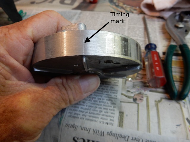
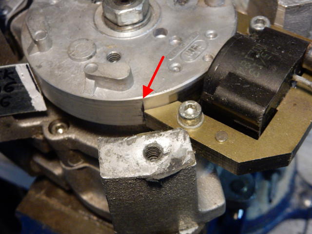
Top 80: Rotate the flywheel so that the mark (about 10mm from the edge of the leading magnet) is even with the
lower coil flange (see photos below). A felt tipped pen can be used to highlight the timing mark. It is possible that the timing mark is missing and, if so, it is safe to set the
timing per the Minari technique given in the next section. After the timing is set in this way, it can be measured accurately by using Method C on the
check timing page.
The nut must be tight enough to hold the flywheel so that it will not be affected by the strong pull of the magnets to the coil. Once the flywheel is adjusted correctly, remove the dial indicator.
Minari (clutched & non-clutched): Make sure the piston is at top dead center and stays there. The flywheel nut must be tight enough to hold the flywheel so that it will not turn relative to the crankshaft due to the strong pull of the magnets on the flywheel to the coil.
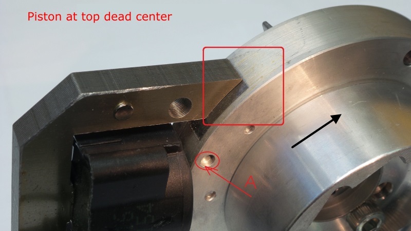
For the Minari clutched engine (and others similar), set the timing by aligning the edge of leading magnet on the flywheel with the trailing edge of the coil as in this photo from Minari. This will give a value of 15-16º BTDC. Note the dimple "A" in the flywheel and its location. It will be used to double-check the timing value.
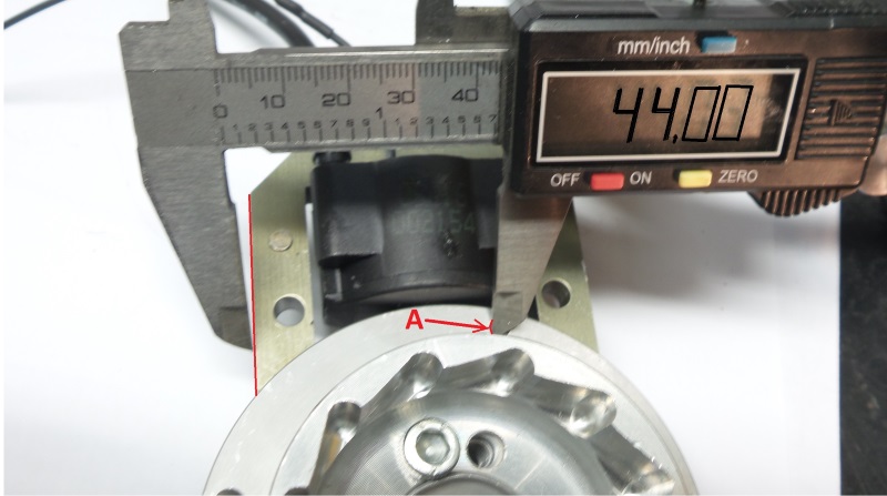
 To double-check the setting for the clutched engine, observe
the distance between the left edge of the dimple on the flywheel and the leading edge of the coil which should be 44.00mm ± 0.2mm.
To double-check the setting for the clutched engine, observe
the distance between the left edge of the dimple on the flywheel and the leading edge of the coil which should be 44.00mm ± 0.2mm.
For the non-clutched engines, Minari has this PDF with photos for setting the timing. Lining up the rear of the leading flywheel magnet with the leading (inner) edge of the coil advances the timing slightly and gives a value of 18-19º BTDC.
Top 80 & Minari: Once the flywheel is in the correct position, remove the dial indicator.
9. Tighten the flywheel nut 38-40 Nm (or your engine's value). Be very careful not to change the position of the flywheel relative to the crankshaft.
Top 80: With the oil wrench filter wrench or the strap method, hold the crankshaft while applying torque. Miniplane makes a special tool for this but it is not easily available. Be careful while applying torque to the flywheel nut. Any relative movement of the crankshaft and the flywheel will change the timing.
Minari and others: Use a wrench on the drive pulley or a socket on the drive pulley nut to hold things as you tighten the flywheel nut.
10. Coil Gap Be sure to check the coil gap. If it is not correct, the timing and coil output will be affected at idle, making the engine harder to start.
11. Check the timing using this method to be sure it was set correctly. Method C is the most accurate way to double-check the timing and uses a timing light and a camshaft timing wheel. The flywheel nut must be torqued to specifications or the flywheel may move relative to the crankshaft when the timing is checked with this method.
12. Reassemble the engine by reversing steps #1 #4. Test flying the engine will ensure that everything has been done correctly. Be sure to carefully observe the peak running temperature. Engine overheating can be caused by excessive retardation of the ignition timing.
![]()